
Accomplished & Goals:
I will be breaking up the accomplishments and goals into three categories, carriage, frame/gantry, and pin board. As all three had progress in either CAD/Design, Fabrication, or Assembly.
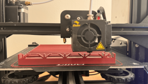
Carriage: I completed a “working” version of the carriage CAD, and began printing it. I split it into two for printing purposes as it was too big for my ender 3. The bottom print of the carriage took 17 hours, and the top took the same. It was crucial to have these done before last Friday as we prepped for demo. I updated the design of the racks to make them longer and the pinions to make them work with the 180 degrees servos instead of continuous ones. I printed 6/32 of the pinions and 4/32 racks.
Once everything was printed, then began the testing. I had to file the carriage down to make the racks slide smoothly, but once finished the racks moved really nicely. The pinions had problems mounting to the servos, so those had to be redesigned once more, and are currently printing.
The carriage works enough for demo, but needs some design changes and to be reprinted. I will be adding lightning holes for both weight, and room for the wires to pop out. I will also be increasing the size of the mounting holes. This redesign will take some time, and so I will allocate a good chunk of next week to it, in order to get it printed on time. I plan to get the design done this coming week and start printing again on Saturday. I also plan to print a majority of the rack and pinions throughout this week .
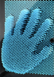
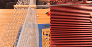
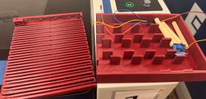
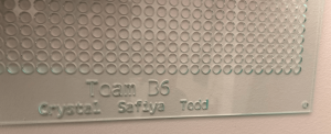
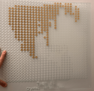
Pin Board: The Pin Board got two iterations this week. I finished the cad of the pin board on Sunday and laser cut it. The outer frame of the board wasn’t large enough to fit on the frame, and needed adjustment, another slight detail was the spacing on the holes, I ended up moving them closer together and fixing some geometry to make the carriage be able to reach all rows of the pin board. It now looks like this, with both boards assembled and spacers in between.
The dowels were calculated to need 5cm of offset, 1/8″*2 for the thickness of the pin board, 1″ for spacing in between boards, and 2 mm of clearance. A few were cut, and put on the board. Next week I hope to order all the dowels we need, and have them ready to cut for the week after.
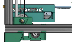
Frame/Gantry: We made some progress in getting pieces for the frame and gantry repurchased, and I believe we have everything except the heat inserts. I made some progress on the full assembly cad, but need to design the gearbox mounts, and the connections between the carriage and the frame. There is also a lot of assembly work to get done, I will hopefully assemble the frame next week and design the gearbox plate and the piece that connects the carriage with the frame.
Progress: On schedule, but a little tight on time for 3D printing and design.