
The most significant risk that could jeopardize the success of the project is when our supplies for the reset mechanism and dowels come in. We are looking into alternatives for the reset mechanism, but the dowels do not have alternatives. No changes were made to the design. I would add pictures but our media quota has been reached.
Crystal’s Status Report – 11/22
This week I cut hundreds of dowels. I still need to cut more when the other dowels come in. This week I also successfully wrote the firmware to control 3 servo motors on the PWM expanders and 2 stepper motors. I was originally having issues with the PWM expander, but the issue was that I forgot to plug it into a power source. When I first flashed the code onto the STM, the stepper motor twitched. This was due to the step pulses being too fast. I then added the stepper motor code but the stepper motors just did not spin. I tried to debug this by unplugging the I2C PWM expander, but the stepper motor started twitching again. This was because with no I2C devices connected, the I2C reader was failing and was blocking for a short period of time. This made the stepping loop slower, allowing the motor to spin. When I reduced the timeout, the stepper pulses became fast again, causing the motor to twitch. So increasing the I2C blocking period was just slowed down the CPU to make the stepping speed possible. The second stepper motor also initially used illegal GPIO pins.
I am on schedule, but I am concerned about the ability to incorporate the reset actuators because that depends on when they come in. We also have not ordered all of the dowels yet because we need to wait for them to restock.
Next week I hope to write the firmware for the second PWM expander and write the button powered interrupt that will trigger the reset.
To accomplish my task, I needed to know how to use the CubeIDE, know how servo motors worked, and understand the ability / limitations of different microcontrollers. I practiced reading data sheets and how to internet search to acquire this knowledge.
Safiya’s Status Report 11/22
Progress:
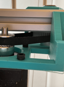
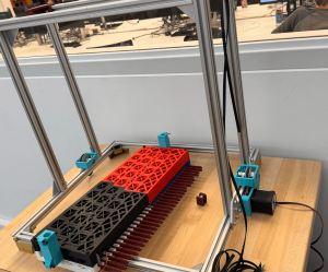
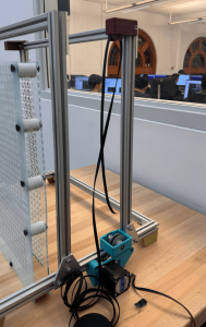
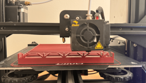
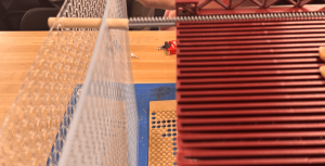
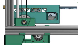
This week was a grind to finish really all the mechanical components of LivePin. I believe it is 2/3 of the way there. There were a few bumps in the design that caused me to take some more time drilling a couple holes to make the gearboxes fit, but so far I have all the 3D Printed parts other than the pinions and reprints of the feet. I was able to assemble the full frame and carriage (without servos), and am now working on the gantry, I assembled 1 out of 2 of the gearboxes and started belting it today. I superglued the bearing plates to the carriage, and am letting it set till tomorrow. I also made edits to the pin board by putting on 10 spacers.
Goals for Next Week: Handoff LivePin to programming on Tuesday at the latest. Finish testing by Sunday. This also includes smaller goals like printing all pinions by Tuesday, finish assembly of gearboxes and belts, as well as assembling the pin board.
On Schedule: Yes but rushing
Question of the Week:
Knowledge I found necessary to learn was research, design, and execution. Although tedious and at times hopeless feeling, research and designing in CAD were so crucial once I reached assembly. The time I put into a thoughtful design is now paying off as the construction comes to life and the moving parts start to fit together. Another strategy is research, I had no idea how to make a “LivePin” or a tool that goes up and down and pushes pins, so I looked for parallels and studied those. I could not find any LivePin type devices, so I looked at how 3D printers are built. That research was the basis of the design and made things work. I also learned to prioritize purchasing even when the design was not as far along as I wanted. Knowing to reprioritize was crucial.
The biggest new skill was talking to people who could help. I introduced myself to laser cutter monitors, Robo Club managers, and the machine shop manager, and they helped with both fabrication and sourcing (bolts and acrylic). Those connections were actually fun and very useful for reality checks. For example, I was ready to 3D print 1,024 pins until a TechSpark woodworker suggested using dowels instead, which saved time and money. These are the strategies I am keeping: Research and design (thoroughly), use your available resources, and learn to reprioritize when necessary.
Tedd’s Status Report – 11/22
This week, I worked on designing the reset mechanism system and gathering all the moving parts that would feed into the system. In addition to refining this subsystem, I began integrating a Raspberry Pi as the primary controller for communicating with the STM32 via UART. The goal of this setup is to reliably transmit the full 32×32 pin array data, ensuring low-latency, error-tolerant communication between the two devices.
To move toward this, I configured the UART interface on both the Raspberry Pi and STM32 and started developing a structured data-packet format to handle the larger pin-array payloads. Looking ahead, I am planning to build a GUI system on the Raspberry Pi to make the user interface cleaner, more intuitive, and maintainable. This GUI will eventually allow users to interact with the depth camera more intuitively and edit and send the 32×32 pin configurations seamlessly. It would also ideally control the reset mechanism as well.
This Thanksgiving break, I am planning on working on the presentation slides as well.
Crystal’s Status Report – 11/15
This week I started working on incorporating the PWM expanders and big stepper motor driver. Previously the servo motors were directly plugged into the GPIO pins of the STM. This would not have been efficient because a single STM does not have enough ports to directly connect 32 servo motors, so we had to buy 2 PWM expanders. Similarly, our stepper motors were previously run on A4988 stepper motor drivers, which did not have enough current to support the weight of our carriage holding 32 servos and gantry belt. I slightly moved the schedule around by working on incorporating these components first instead of programming an interrupt for the rest mechanism. I am still on track. Next week I hope to have all 32 servos working on the PWM expanders and the stepper motors on the heavy duty driver.
Safiya’s Status Report 11/15
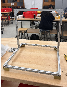
This week my priority was Frame/Gantry Assembly and 3D printing. I made significant progress and am proud to see the design from CAD coming to life.
I printed the feet of the frame and partially assembled the frame of LivePin. I also finished the hopefully final design of the carriage, where I added lightning holes, made the mounting holes. for the servos bigger, and increased the size of the rack slides to allow for easier sliding this time around. I finished printing it! And now need to assemble it on Sunday and design the mount for it onto the frame.
I also printed 16/32 racks, no pinions yet, and printed most of the components. I aim to finish 3D printing by this Wednesday. I also aim to have the frame completed by Sunday, and mount the carriage and belt by Friday.
I am a little rushed for time, but I am ahead of the schedule on the update Gant Chart.
Team Status Report – 11/15
This week, we had our demo presentation. We think that our demo went pretty smoothly and the feedback we received was relatively positive. I think we need to work on getting the hardware components finished and printed so that we can connect all the pieces together to get a minimum viable product. Because I had to use the Intel NUC and not the Raspberry Pi that was given, I will need to move all the scripts and the files to the Raspberry Pi and make sure that it can communicate with the STM32 via UART. Crystal and Safiya need to continue working on the firmware and hardware components and finish cutting the dowels and complete the gantry system.
For validation, we need to do more user tests, specifically of the image that is outputted on the pin art board. We will do this by asking a bunch of people if they can see the image that is supposed to be outputted on the board. Additionally, we will do validation for the gantry system and the pin actuator system to ensure that they will push at a certain distance, given an angle. We will ensure that actuators are push pins to the intended heights 95% of the time. We will also make sure that the gantry will move down the belt consistently and with precision and accuracy.
———————————————————————————————–
For Verification of the mechanical subgroup, we will need testing of the gantry, the pin board, and the carriage. For the gantry we will we have the carriage travel up the gantry successfully 5 times, and be reset to its limit switches at the beginning and end. We will also make sure 10 times in a row the carriage travels to the correct row that is authorized by the code.
For the carriage specifically, we will test 3 different combinations of rack and pinion motions. The test will consist of full retraction of all actuators, full extension of all actuators, and actuators at different depths.
For the pin board, we will test that all pins are stable and able to be controlled by displaying 2-3 images of varying depths and checking through 1/3 of the pins to verify a sample set that the pins are working as they should and are stabilized.
———————————————————————————————–
Tedd’s Status Report – 11/15
This week, we partook in demos, which was split up between two main subsections. We had the software component, which showcased the depth camera and the python script that I wrote. We also had the firmware and hardware component, which tested the actuators pushing to max distance. Because our Raspberry Pi did not work before demos, I had to make use of my Intel NUC in order to get our script running and to be able to showcase the work on the software side.
After demos, I was in charge of moving the script to the Raspberry Pi, just so that we won’t have to make use of the Intel NUC in the future. I am also in charge of the UART communication between the RPI and the STM32. Additionally, I am in charge of the reset mechanism, and I drew out plans to get the reset mechanism working. Here is my planned diagram: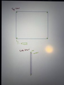
As we move towards Thanksgiving break, we are hoping to be able to assemble most of the parts and have a fully working product in the next few weeks.
For the verification system for the software components, we need to make sure that the depth camera is properly calibrated and can display images clearly or at least get enough details to output on a pin board. We will do a bunch of user tests to verify that the image that is outputted is indeed visible. This will be done specifically by asking random people if they can see images are visible, given a diagram of pixels that are shaded in.
Safiya’s Status Report 11/8
Accomplished & Goals:
I will be breaking up the accomplishments and goals into three categories, carriage, frame/gantry, and pin board. As all three had progress in either CAD/Design, Fabrication, or Assembly.
Carriage: I completed a “working” version of the carriage CAD, and began printing it. I split it into two for printing purposes as it was too big for my ender 3. The bottom print of the carriage took 17 hours, and the top took the same. It was crucial to have these done before last Friday as we prepped for demo. I updated the design of the racks to make them longer and the pinions to make them work with the 180 degrees servos instead of continuous ones. I printed 6/32 of the pinions and 4/32 racks.
Once everything was printed, then began the testing. I had to file the carriage down to make the racks slide smoothly, but once finished the racks moved really nicely. The pinions had problems mounting to the servos, so those had to be redesigned once more, and are currently printing.
The carriage works enough for demo, but needs some design changes and to be reprinted. I will be adding lightning holes for both weight, and room for the wires to pop out. I will also be increasing the size of the mounting holes. This redesign will take some time, and so I will allocate a good chunk of next week to it, in order to get it printed on time. I plan to get the design done this coming week and start printing again on Saturday. I also plan to print a majority of the rack and pinions throughout this week .
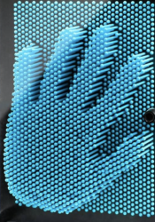
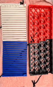
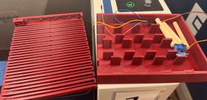
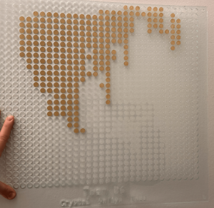
Pin Board: The Pin Board got two iterations this week. I finished the cad of the pin board on Sunday and laser cut it. The outer frame of the board wasn’t large enough to fit on the frame, and needed adjustment, another slight detail was the spacing on the holes, I ended up moving them closer together and fixing some geometry to make the carriage be able to reach all rows of the pin board. It now looks like this, with both boards assembled and spacers in between.
The dowels were calculated to need 5cm of offset, 1/8″*2 for the thickness of the pin board, 1″ for spacing in between boards, and 2 mm of clearance. A few were cut, and put on the board. Next week I hope to order all the dowels we need, and have them ready to cut for the week after.
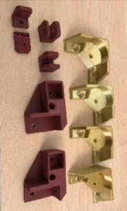
Frame/Gantry: We made some progress in getting pieces for the frame and gantry repurchased, and I believe we have everything except the heat inserts. I made some progress on the full assembly cad, but need to design the gearbox mounts, and the connections between the carriage and the frame. There is also a lot of assembly work to get done, I will hopefully assemble the frame next week and design the gearbox plate and the piece that connects the carriage with the frame.
Progress: On schedule, but a little tight on time for 3D printing and design.
Crystal’s Status Report – 11/8
This week I was able to somewhat concurrently run 4 servo motors and then sequentially run the stepper motor that powers the gantry. I am saying somewhat concurrently because timer 2 on the STM only has 3 usable channels. This leaves one of the servo motors running on a different timer, causing it to run out of sync with the other servos. I am investigating how to sync these two timers. While writing the stepper motor driver, I realized we never considered a stepper motor driver in our design. Given that our stepper motor will need to support the weight of the actuator carriage and 32 servo motors, I decided to purchase a heavy duty stepper motor driver. I also wrote a function that can convert the calculated depth to an angle the servo can rotate to. We also decided to use dowels as our pins. We tried hand sawing and using a miter saw to cut the dowels. The miter saw didn’t give a clean cut, so we will be hand-sawing for now. However we will try other saws.
I am on schedule. Hopefully, the pwm expanders will come in this week, so I can implement actuation with the pwm expanders.