Safiya’s Status Report 10/25

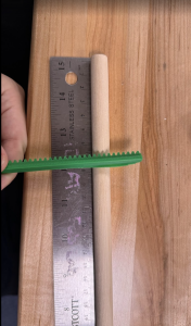
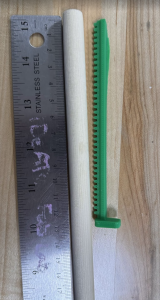
This week I pushed purchasing and fabrication forward. I  submitted all purchase requests for the frame and motion system, revised the cart to swap in cheaper equivalents, and removed a few non-essential frame parts to stay in budget. I also brought my 3D printer back online and printed a first rack-and-pinion set, the print has defects, so I started tuning the printer. On the pin board, I went to TechSpark planning to laser cut but they didn’t have the right sheet size. I checked Ideate and confirmed they have acrylic that fits. Back on CAD, I re-checked cost and realized 1,024 dowels would strain the budget, so I explored alternatives: bulk chopsticks were cheap but too small in diameter, at Robo Club I found PVC stock that could work. I contacted the shop manager to request material.

I’m generally on schedule for frame and motion procurement, but the pin board is waiting on final material choice. To stay on track, I will finalize the pin diameter and hole pattern as soon as I hear back on the PVC, size the laser files accordingly, and cut at Ideate. In parallel I’ll finish the printer tuning and re-print the rack and pinion so mechanical tests are not blocked.

My Goals:
Finalize pin-board design with confirmed pin material and diameter, plus laser ready DXF.

Pin board laser-cut at Ideate and a small assembled section for testing.

Reprint, clean rack-and-pinion set and a short note on print settings and tolerances.

Updated BOM with actual unit prices from the approved frame/motion orders and removal of the unused components.


Tedd’s Status Report – 10/25

This week, I continued developing the depth visualization pipeline using data from the Intel RealSense camera. Building on the preliminary script, I refined the depth-to-plot conversion process to improve the accuracy and consistency of the pin actuation map. I also explored adjustments to the camera’s resolution and filtering parameters, which may lead to noticeably better definition for complex shapes, but it is still a work in progress.

In addition to improving image quality, I began automating parts of the workflow so that depth data can be processed and plotted with minimal manual input. This will streamline testing and make it easier to integrate real-time data processing in future iterations. Overall, the updated system is moving towards a more clearer visual output.

Team Status Report – 10/25

The most significant risk that could jeopardize the success of our project is our project. Some items for the gantry exceeded expect cost of the corresponding items. Due to this concern for budget, the size of the pins might be changing. We are finding alternatives through Ideate, RoboClub, or a more affordable pin solution like straws or chopsticks. Everything for the frame and gantry motion of live pin was ordered and we are waiting on delivery. In terms of the Cad there are some design changes being made to the frame to accommodate for 32×32 frame instead of 32×24. The file for the pin board was made and is ready to laser cut. We found cheapest material at ideate but are waiting to laser cut until we have a finalized pin size based off our budget/supplier.

Crystal’s Status Report – 10/25

I am currently trying to drive 4 servo motors. I was originally using 18349 code as a base, but was unsuccessful. I decided to pivot to using STM32CubeIDE projects because there are more resources on how to debug and approach common projects like driving servo motors. As I was trying to drive the servos, one of the servo motors had damaged wires due to strain and was therefore unusable. Setting up the CubeIDE was a bit of a challenge at first. The program was unable to detect my ST Link Server, and therefore unable to connect to my STM32. To fix this, I had to redownload the latest version of the CubeIDE. I was able to drive 3 servos! If I had a 4th servo, I am confident I will be able to drive it too.
I am now on schedule and next week I hope I can help with the physical assembly of the project.

Safiya’s Status Report for 10/18

  1. I finished the CAD for the carriage subsystem. I started fixing my 3D printer to get ready to print rack and pinions. I also put in purchase requests for all items so far to assemble LivePin. I had to also redo the CAD for the frame because we went from 32×24 in the CAD to 32×32 pin board.
  2. Behind. Purchasing might take a bit. To get ahead I will ensure all items are ordered that we need for a working demo, and get the CAD to a point where all pieces are accounted for.
  3. Fully Finished CAD, 3D printed rack and pinions, and finished purchasing.

Tedd’s Status Report – 10/18

This week I worked on getting a visible plot from depth coordinates provided by the Intel Realsense. With my preliminary python script, I was able to run OpenCV and matplotlib to get a pretty good output of which pins should be actuated and the distances that each pin should be actuated. Here are a few examples below:

As you can see, the depth camera was pretty accurate and is able to capture simple objects and display them pixelated on a plot. However, I realized that more complex objects like faces are not well translated onto the plot. I might have to fix up the resolution of the depth camera and see if that could help us get better results. For now, this is a preliminary script and it seems to be working well. I will automate this process in the future as well.


Crystal’s Status Report – 10/18

I was able to get the LEDs to vary in brightness demonstrating a PWM signal. I am experimenting with different approaches to get 4 servos moving in parallel.

I am behind schedule. I will try to put in more hours to get more progress. Next week I hope to be able to have 4 servos moving in parallel.

Team Status Report – 10/18

A – Our product is a low cost alternative to other motorized pin displays. Our low cost and modular approach enables accessibility that can be sourced internationally, allowing replication in museums worldwide. This open and scalable approach encourages cross cultural collaboration in art installations. The ease of use enables users who are not well versed in technology.

B – LivePin is designed with sensitivity to cultural diversity and inclusivity in communication and collaboration. As an interactive system for museums and for children/adults, the device enables users to communicate three-dimensional ideas without reliance on a shared language or cultural context.  This visualization system reduces the potential for misinterpretation of visual or linguistic descriptions and promotes equality regardless of language proficiency. Moreover, by enabling hands-on, physical interaction with digital content, LivePin aligns with cultures that value craftsmanship and learning. The design also respects differing cultural expectations of professional communication by providing a neutral, technology-driven medium for expression and art.

C- Our solution addresses the need for rapid, tangible 3D visualization in classrooms and small exhibits without generating one-off physical waste. Instead of printing and discarding plastic prototypes for every iteration, the system renders forms on a reusable pin board, then resets for the next concept. This directly reduces consumables (no filament, supports, or failed prints) and cuts the time and material tied up in single-use models, while still giving viewers a clear, physical sense of shape and depth.

Environmental considerations are built into the design. The frame uses durable, recyclable aluminum. The guide plates are laser-cut for low scrap, and the pins are wooden dowels that are inexpensive, repairable, and biodegradable. During operation, staged actuation keeps power draw modest relative to continuous additive manufacturing, and the system produces no consumable byproducts once a visualization is complete, the board simply resets. Taken together, the design conserves materials, lowers operational waste, and supports responsible end-of-life handling through reuse and recyclability.

A was written by Crystal. B was written by Tedd J. C was written by Safiya

Safiya’s Status Report 10/4

This week I focused on our design presentation and hardware planning. I practiced the presentation several times, and moved the bill of materials forward by organizing parts by subsystem, choosing likely vendors, and building rough cost totals. I also updated CAD for the larger pin screen and produced visuals for the presentation.

I am a little behind on final pricing and carriage design. To catch up I will lock vendor choices, complete the latest bill of materials with totals and start the first round of orders so the build stays on track.

Next week I plan to finalize the bill of materials, finish the carriage design and  begin 3D printing the rack and pinions.

Crystal’s Status Report – 10/4

This week I started getting the STM32 setup by configuring the timers and GPIO pins to generate a PWM signal. This has not been successful yet, but I will verify the setup by output putting the PWM signal to an LED.

I am slightly behind on schedule due to workload from other classes. I will put in extra hours this weekend to get the LED to vary in brightness with duty cycle, demonstrating the PWM signal.
Next week I hope to be able to have 4 servos moving in parallel.