
This week, we made sure to get the design presentation down. We broke down the design presentation into different parts, and for the presentation, I took the use-case requirements and the testing and verification portion. We also took feedback from other groups from our proposal presentation, and realized that we need to add more numbers and be more thorough in our explanation. This week I also looked into the Intel Realsense, but realized that it is not fully compatible with Macs. So I will be waiting for the Oak-d Pro to be lent to us as it is fully compatible with Macs.
Safiya’s Status Report 9/27
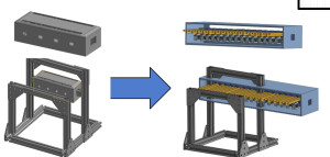
This week I spent a lot of time on Onshape CADing and redesigning. The original CAD that I started earlier in the week derailed a bit, as we got to discussing some design changes, specifically centered around increasing the resolution of the PinScreen. As it scaled up, the frame and gantry and carriage all had to scale up as well. We then decided on Monday to make a custom PinScreen instead of buying a COT one, and thus that led to needing to design and CAD the PinScreen. I am not totally done with a lot of the details (haven’t started the reset mechanism). But this is the progress so far on the cad :


Deliverables for next week would be a complete Bill of Materials, Purchasing done, and a more fleshed out CAD that is ready(ish) for assembly. This includes the design and CAD of the carriage 3D print, which is the most complicated, the motors and belts on the frame, and the pinScreen reset mechanism.
We are pretty good on schedule so far.
Team Status Report 9/27
After further designing our project, we identified several risks. A big concern is actuator reliability. The RC servos may stall, strip gears, or fail to deliver our desired accuracy under load. To mitigate this we will do early bench testing of the servos with the rack and pinion to see if they can deliver the desired results. Another concern is gantry misalignment.
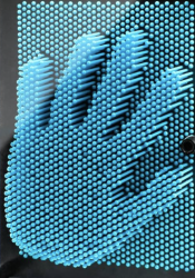
A significant change we made to our design is scaling up our design from 16 x 16 pins to 32 x 32 pins. This change was necessary due to concerns of low resolution. Though you can see Abraham Lincoln with 16 x 16 pins (image below). We originally decide to only have 16 x 16 pins to comfortably afford 16 actuators, but with a more detailed bill of materials we concluded we could afford 32 actuators.

Part A:
The primary purpose of our solution is for entertainment that brings a familiar pin toy concept into a dynamic, automatic form. From a health and well-being standpoint, it offers a playful, low-stress form of interaction. Unlike more physically demanding entertainment technologies, the system is hands-free and does not require repetitive strain, making it safe and comfortable for users of all ages.
Safety is carefully addressed in both mechanical and electronic design. The pins are covered by an acrylic pane to prevent accidental pinching or injury. Furthermore the reset button acts moves the device into a safe state where pins are reset. Protective housing and controlled motion paths further reduce hazards, ensuring that the entertainment experience remains safe and reliable.
Part B:
Our product solution is designed to foster social connection and shared experiences through entertainment. By transforming the classic pin-art toy into an interactive, automated and affordable display, it creates a platform where groups of people can gather, observe, and engage with the visual output together. This collective interaction encourages conversation, collaboration, and bonding. The system therefore becomes more than just a device. It becomes a medium for social engagement.
Culturally and economically, the product is designed to be versatile and accessible. Its modular, scalable design allows it to be deployed in diverse settings, from well-funded institutions to smaller community organizations, ensuring broader access regardless of resources. By supporting creative expression across different cultural contexts, the system respects and enhances how communities organize around shared interests such as art, technology, or education. In this way, the device not only entertains but also reinforces social ties, offering a playful and inclusive means for people to connect across age groups, cultural backgrounds, and social organizations.
Part C:
A big focus of our project was creating a 2D to 3D display while being affordable. As any projects that were done before that had actuating pins were extremely expensive and thus making it out of reach for casual applications and environments, such as schools and homes. To accomplish our goal of a live pinScreen, we had to create a mechanism that would push each row of pins, which is mechanically more difficult, but in the long term it is cheaper and more accessible.
Additionally our design controls cost by using a shared actuator head instead of one motor per pin, so resolution scales mostly with low-cost passive parts rather than expensive motors, drivers, and power. Major cost drivers are the frame/linear hardware, a small set of servos, and the depth-camera/Pi. Operating costs are low , and the architecture lets us scale up affordably by adding pinScreen tiles without redesigning the actuation/control stack.
A was written by Crystal, B was written by Tedd and C was written by Safiya.
Crystal’s Status Report for 9/27
This week I continued designing the actuator subsystem of the project. We decided to use a RC servos to power rack and pinions that will actually push the pins. However, each servo would need their own continuous PWM signal and using 32 independent channels directly on one STM is impractical. This means we need an external PWM driver IC.
We are still on schedule. We hope to order parts by the end of next week.
Crystal’s Status Report – 9/20
So far, I’ve worked on shaping the project by carefully identifying the right components and mechanisms to make it feasible. I started by analyzing the cost and scalability issues of giving each pin its own actuator, realizing that this would exceed our $600 budget, so I explored alternatives like row-based actuation and column scanning. This week I listed different position based actuator parts we could use and narrowed it down to a few. On the electronics side, I mapped out how to divide responsibilities between a Raspberry Pi (for real-time depth capture and heightmap processing) and an STM32 (for deterministic actuator control), since the Pi can’t handle precise timing and the STM32 can’t handle heavy vision workloads. I also investigated specific ways to test latency, weighing options like software timestamps versus high-speed video, to ensure I can measure each subsystem’s delay as well as the full end-to-end pipeline.
Tedd’s Status Report – 9/20
This week, I looked at the various computer vision libraries that were compatible with our project. I am not sure which depth camera we will be using, so I am assuming that we will be using the Intel Realsense camera. Right now, we are tasked to work on the design of our product, which means that we will need to look over all our design choices for the gantry and the actuators. I looked into which computer vision libraries may be useful for our project, which will include the height map as well. Right now I think we are right on schedule.
Team Status Report 9/20
The most significant risks that could jeopardize the success of the project might be the complexity of the design. Mechanically and Electronically it’s a little complex and out of our comfort zone, the most difficult part that could risk the feasibility is most likely the integration and getting software + firmware + hardware all working cohesively. To manage these risks, we are doing our best to separate each category of the design into different areas of responsibility so that each person will be accountable and an “expert” at their tasks. This will help us when debugging when it comes to the integration stage. Our contingency plan would be scaling down, we are prepared for the firmware and software part to be complicated so we are prepared to drop the “updating” nature of LivePin, and start with pre fed images to replicate on the board, without the human aspect and the “live” feature.
Yes, through concept sketching we found that some sort of clamping mechanism was necessary for the pinboard to stay upright, and we also found the need of limit switches in our design to mitigate the risk of the gantry from damaging itself, and also for the carriage to be able to “home” itself. This change was very necessary, in order for us to have a way to initially find where the carriage is in terms of its cartesian coordinates. This incurs the cost of a couple limit switches which are relatively cheap (less than 15 bucks total).
Safiya’s Status Report for 9/20
- This week I created concept sketches for the LivePin Prototype and did a lot of research on all the components that it would take to come up with a comprehensive design. I looked into some actuator options and think the place to start would be a 3d printed rack and pinion. I also started sketching out the carriage design and the gantry system, which brought up a lot of design questions, which is good so we can answer them before moving forward. I included that concept sketch doc here.
- My progress is on schedule, as we planned for me to do the concept sketch this week and then finish CAD by next week.
- I hope to complete the CAD of the prototype in time for the design presentation and complete the design presentation.This one is not the final, it won’t let me upload because its too big
Note Sep 18, 2025


Introduction and Project Summary
As an initiative to make museums and art exhibits more interactive, we propose to build a real-time 3D reconstruction system through a pin art board, called LivePin. This device will allow a user to place any 3D object in front of a camera in order to reproduce the image as a tactile 3D impression on a pin art board. Before you would have to physically press onto a pin art board to make it move and create an accurate impression, but now with our system, all you need to do is hold something in front of a camera and the pins will move automatically. We aim to design a budget friendly and efficient automated pin art board that captures the nostalgia of this wonderful childhood toy and turns it into a more technologically advanced interactive display. Additionally, while there are existing display boards that utilize a similar concept (like flipdot displays), there is no known device that moves pins automatically to create interactive designs. As a result, we hope to bring this unique idea into fruition for the future of museum and art exhibits as well as for children around the world.