Completed CAD model with water loop and other component models downloaded from online (e.g. SSRs, DC-DCs, etc.)
Adjusted radiator + fan position to reduce board size
Planned out and added power planes (24V power supply stepped down to 12V, 5V for fan/pump, servo)
Began 3d printing some parts from CAD design
Full AssemblyFull Assembly – Bottom ViewWater LoopHeater Complex (Power Resistors)Servo Valve Assembly (Blockage Fault)
Power Distribution
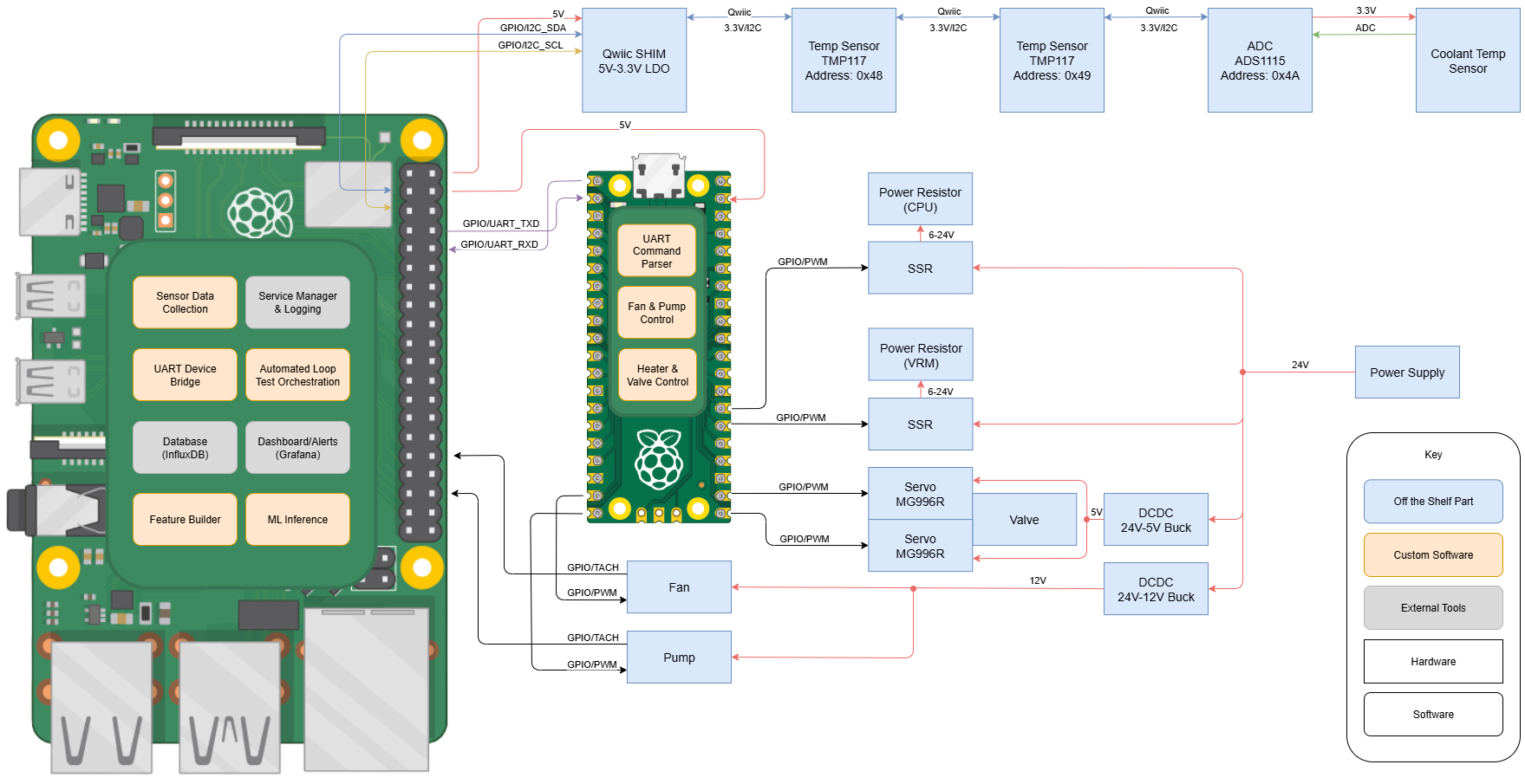
Block Diagram
Finalized block diagram to add power supply and conversion
Adjusted coolant temp sensor connection to separate sensor data collection from controls (fan/pump, valve, heater)
Added software
Block Diagram
BOM Draft
Completed BOM, added case components like linear motion rods and connectors
Added power components like DC-DC converter, power supply
Schedule & Progress
Updated schedule to account for part lead times
Need to order parts ASAP since fabrication for laser cut parts depend on dimensions of actual mounting holes