Andrew’s Status Report for 12/06/2025

This week I accomplished a lot with this project. I replaced the temporary putty that was attaching the wheels to the DC motor with epoxy putty, which is now there permanently and there is no wobble at all during the spinning. I finalized the entire ramp and the ball rolls smoothly into the wheels and consistently follows the same track throughout all rolling tests. I helped Miles program the robot motors and spin its wheels, allowing it to go forward, reverse, right, and left. I bought four 12V 20Ah car batteries and a charger for those to directly connect it to our 2 DC motors, which take in 24V and 18A each. This is the backup option due to the newest motor control board breaking. I am connecting two 12V batteries in series for each motor to achieve 24V and put the DC motors at maximum power. Finally, I am currently building a funnel and double ramp system that holds 11 tennis balls and programming a servo with Miles to only let 1 ball drop/shoot at a time. To elaborate on the double ramp system: the ball slowly rolls down a shallow ramp at first into the servo and then quickly rolls down the steeper ramp into the motors, helping to achieve the 1 ball drop at a time.

My progress earlier this week was super behind due to our new motor control board breaking again, but I, along with my group, have made significant progress the past few days with CV tests, structure design, robot motor controls, launch tests, and overall integration.

Since final demo is coming up, I hope to finish the last touches of the structure, integrate the servo with the CV, and finally do extensive launch tests with the new batteries.

Andrew’s Status Report for 11/22/2025

This week, I built almost the entire structure of the launcher mechanism. I cut the PVC sheets into the necessary size that could fit the DC bike motors and be drilled into the sheet. The robot base arrived, so I was also able to drill the PVC sheet with the motors onto it. Since the screws holding the motors would touch the robot wheels which would collide when there is any movement, I utilized another PVC layer to create more spacing. I drilled indents between the PVC sheets to ensure a perfect fit for the screws and found the balancing point between the launcher and the base to ensure that when the robot rotates/moves, both motors will be experiencing the same load and not one is more stressed than the other. I was also able to test the launcher at 10% power and it reached about 1.5 feet (35 Watts). This means that we can at least launch 15 feet if there is a linear increase. The only thing that is missing is the feeder mechanism that rolls the ball into the spinning wheels, which will be worked on in the next few days and will be held together with epoxy glue that can support up to 3300PSI. Also, the wheel attachments are currently attached through basic putty, which can only support 2 pounds of force and it is unstable from how fast the wheels are being spun. Epoxy putty, which creates a metallic-like finish and supports up to 4000PSI, will be used for the final wheel attachment to ensure permanent stability. I may also try testing different wheels with different coefficient of frictions and hardnesses to examine which one gives the farthest launch.

I would say my progress is on schedule. I should be able to finish the whole structure build in the next few days, and then with the new motor control board in, I will be able to test the total launch distance.

Next week, I hope to complete the whole structure: ball feeder, epoxy putty and epoxy glue to hold the physical components together, and drill more areas for components like camera/Raspberry Pi placement. I hope to be able to test the launcher at full power and start the hardware/CV integrations.

Some new tools/knowledge I found necessary to learn to be able to accomplish my tasks is 3D printing the wheel attachments, overall materials for a strong structure build, and physical constraints of a launcher. Since Miles has the CAD program on his computer, I was able to learn from him how to import 3D print models, design/size the components, and learn different 3D material types and infills to ensure the final product meets the requirements for our launcher. I watched a few YouTube videos and read physics textbooks as well to refresh physics calculations and tradeoffs for the launcher mechanism. Through these videos and readings, I was able to calculate the overall exit speed, RPM, exit energy, power, and torque necessary to launch a tennis ball at 45º 20+ feet. Finally, I watched YouTube videos on what materials I needed to use to build the whole launcher. This is where I learned about epoxy glue, epoxy putty, and PVC sheets which is currently holding up the build quite well.

Here is the progress of the overall project without the boards connected yet:

Andrew’s Status Report for 11/15/2025

At the beginning of this week, I contributed in presenting during the Interim Demo on Monday and Wednesday. Our original motor control board broke down and the temporary board suddenly got delayed in shipping, but I was able to help set up the replacement board for Wednesday’s demo once it came to give the staff a better view of how the DC bike motors will be operated. Following the demo, I started to build the base using PVC pipe, PVC sheet, and thinking about the gears to buy. However, due to a limited timeline and not wanting to take any risks of building a rotating base that may potentially break down or not work, I helped decide to use a robot for the base instead. The robot has its own motor controls and wheels, meaning that it will be able to be mobile and make it easier to rotate as well as travel around if our launcher’s range is limited.

My progress was initially behind, but after shifting to the robot base, it makes the project timeline more achievable. Rather than having to rely on completely building a base from scratch with gears, ball bearings, and stepper motor that may not even work until it is finalized and tested, I believe that having a robot makes our project completable in the coming weeks since it is already a built structure. The robot needs to have its wheel motors coded and have the launchers and camera reintegrated on top of it.

Next week, I hope to rebuild the launcher onto the robot base once it arrives. Currently putty is being used to stabilize the wheel attachments on the DC bike motors, so I plan to use some form of press fit + strong glue to make it better. Following the physical build, I hope to help Miles with the motor control code for both the launcher and the robot. The CV is basically finished so motors and overall integration are the biggest priority.

With a temporary launcher built and applying low wattage (around 10% of the motor’s max of 350W), the ball launches around 2 feet. Also, the temporary putty with the wheel attachment seems to be stable when launching a ball at low power. The 45 degree angle attachments for the base of the motors also hold up and so far gives the desired launch distance as calculated by my physics. With all of these temporary and low power implementation, I am confident that in the coming weeks when better parts arrive and I can finalize the build, the ball will be able to launch 20+ feet at 45º as proposed. When the structure is completely built, I will apply max wattage to the motors and see how far the tennis ball launches with respect to a 20 foot marker/tape on the ground. If it does not reach 20+ feet, then adjustments such as reducing/increasing the angle of launch or using different materials for the spinning wheels may be tested for example. If these alternatives do not work, then testing robot mobility to reach a target rather than overexerting a launch distance is another option.

Team Status Report for 11/08/2025

The most significant risks that could jeopardize the success of the project is still the actual launcher mechanism, but it is not as severe as last week since we are already building it. With the 3D printed wheel attachments, 45º angle connectors and screws, PVC pipe/sheet, and putty, we are able to attach the wheels to the axis of the bike motor and use putty for stabilization and strongly attach the motor base at a 45º angle. The PVC pipe is very sturdy, which makes us feel more confident about our structure compared to the 3D printed design. A small risk would be that we are currently using temporary solutions for some parts. The PVC sheet, which acts as our base lid, did not arrive in time this week so we are using a temporary solution to attach the motors and create a distance between them to launch a tennis ball. The motor control board we borrowed from the ECE department is also not working, so a temporary one that has an on and off switch and potentiometer speed control is being used. However, these are mainly used for interim demo and once we have better working parts come in, we are confident in having everything work and integrated as intended. Pictures of current setup are included below.

No changes were made to the existing design of the system. We have updated our new schedule/ghant chart below. We are back on track with our progress after the setback from last week.


Gannt Chart – Interim Demo

Andrew’s Status Report for 11/08/2025

This week I made much more progress on building the launcher mechanism after the new parts arrived due to complications mentioned in the last status report. Specifically, the parts are the 3D printed wheel attachments, 45º angle connectors and screws, PVC pipe, and putty.  The 3D printed wheel attachments fit perfectly in the middle of the wheel, with very high friction such that the wheel does not slide up and down, and attaches smoothly onto the shaft/teeth of the bike motor axis. Since the bike motor has a rounded bolt that extends beyond the teeth, the wheel would wobble a little. I inserted putty into the 3d printed attachment to fix this issue and ensure the wheel spins stably. I connected the bike motor base to four 45º angle connectors with corresponding screws and separately them to the distance of a tennis ball diameter to make sure it can launch it. The PVC sheet that will be used as the lid of the base has not arrived yet, so I stationed the motors on a cardboard box/plastic container lid temporarily for interim demo. I also helped Miles work on the motor control of the launcher. The motor control board borrowed from the ECE department is not working properly and possibly broken, so a new temporary one that has a potentiometer speed control with an on off switch was bought and I helped Miles incorporate it into our project. I would say the launcher mechanism, even though it is not perfect and a few parts are temporary solutions, it is ready for interim demo. In the next few weeks, I am confident that we can easily replace the temporary parts with better and permanent ones that work similarly.

I would say my progress is now back on schedule. After the compilations mentioned last week about 3D printing the structure, I found that buying parts like PVC pipes/sheets and 45º angle connectors instead of 3D printing them made the process more straightforward. The structure is much more stable, something I worried about with 3D printing. My focus can now be more on how to improve the launch of the tennis ball and integrate the different major parts of the project, rather than if physical parts are going to break or not.

Next week, I hope to get started on the base rotation (x-axis) by purchasing gears to attach to the inside of the PVC pipe. I want to help Miles with controlling the stepper motor to rotate the base since the launcher can shoot a tennis ball now, while John works on the CV. Finally, I am going to try to replace the temporary parts with permanent ones and try to maintain or improve the launch of the tennis ball.

Team Status Report for 11/01/2025

The most significant risk that could jeopardize the success of the project is still the launcher mechanism. We still cannot be entirely sure how well it will launch until a prototype is built. We are working on finalizing a base that will hold the DC motors and tilt it 45º and creating an attachment between the wheels and the motors for spinning. Once these are put together, we already found a library that works with C and Python for the motor control code to launch the tennis ball.

The main change we have made this week is how we plan to assemble the launcher. We realized that an entirely 3D printed design would not be feasible. It is too expensive at around 65 cents per gram, and it cannot print over 175g, which our base weight significantly surpassed.  Instead, we will only be printing the more precise components like the gear mechanisms and the attachment between the wheels and DC motors, and we will be using PVC pipes and sheets for the outer housing and base lid. This will confidently allow for a  stronger foundation at a cheaper price compared to PLA 3D printed material and a guaranteed (and wider if needed) diameter. Other than the material change, we still plan to use the same lid rotation for the actual design, just no longer fully 3D printed. As stated earlier, it is much cheaper to use PVC over PLA 3D printing, which gives us much more flexibility in purchasing other products in case situations similar to this occur down the road.

There are no changes in our schedule. We just need to try complete building the launcher mechanism as soon as possible for the interim demo and integrate other components in (draft CV and motor control code).

Andrew’s Status Report for 11/01/2025

All of the parts came in this week (both DC bike motors, battery, and wheels). I was able to start building the launcher mechanism and finalized the design/placement of components such that it would fit and work smoothly once the base is made. I also helped John look over the draft of the Oak-D Pro CV code, which is still the same and just needs to be actually tested. I also helped Miles work with a library that is compatible with C and Python for the motor control code, which is straightforward and should be implemented quickly once the launcher comes together.

I would say my progress is a little behind. The 3D printed base is still not here, and it may not be made since it is too expensive (65 cents per gram) and the 3D printers cannot print anything over 175g (the weight of our base is significantly above this due to our 10″ diameter). As an alternative for the base that will house the DC motors and tilt it 45º, I decided to opt into using wide PVC pipes and sheets instead. This is not only cheaper, but it can guarantee us structural integrity that we were unsure of with 3D printing PLA material. I also discovered that the wheels cannot directly connect to the DC motors’ shafts, which means they cannot spin yet. To fix this issue, I helped Miles 3D print a model that acts as an attachment between the motor and wheels. Once the base is made and the wheel attachments are received, alongside the motor control code already at hand, I believe that the launcher can easily be finalized. I can then test the launched distance and tune the DC motors to the correct RPM, torque, and power to generate the exact exit speed and energy.

Next week, I hope to have the launcher mechanism finished. I hope to have the DC motors attached to the base, wheels connected on and spinning, and the tennis ball being able to actually launch it around 20 feet for the interim demo.

Andrew’s Status Report for 10/25/2025

This week, I completed the individual as well as the team portions of the Ethics Assignment.  I helped Miles put in the orders from our BoM and I have just started the initial building process of the actual launcher mechanism (integrating the wheels, bike motors, tennis balls, and battery together). I also helped John with the CV program, depth AI, and targeting coordinates that will be completely done on the Oak-D Pro camera’s processor rather than the Raspberry Pi, which is just as capable and seems more of a practical approach and less interfacing involved. Finally, I helped Miles submit the order for the 3D printing of the base of the launcher, which will house the motors that control the X-Axis rotation and the Raspberry Pi.

My progress is currently on schedule, especially since I am starting to build the launcher mechanism this weekend and should be able to test if my physics hand calculations are correct soon.

Next week, I hope to continue building on the launcher mechanism and have it mostly working, while also assisting my teammates with the CV program and interfacings between the camera, Raspberry Pi, and motors.

Team Status Report for 10/18/2025

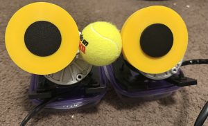
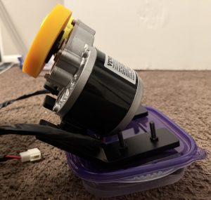
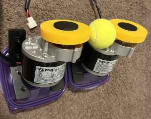
The most significant risk that could jeopardize the success of the project is still the same, which is having the launching mechanism work. With the Design Report and all the physics calculations done, now we have to build the launching mechanism to see if the math follows following fall break. To mitigate the risk, we have purchased have a bike motor that significantly overshoots all of our finalized specifications to ensure we have room to make adjustments in case there were unexpected physical constraints. Furthermore, the Design Report has a section on Design Trade Studies, where there are other approaches to the launching mechanism discussed. If the spinning wheels do not work as intended no matter what we adjust, our contingency plan is to use a spring system that contains guaranteed energy.

No changes were made to the existing design of the system. We are also currently on schedule, so there are no updates to report. Following fall break, we will have our focus entirely on building the launching mechanism, figuring out CV, and working with our motor control board, so we are confident in our current progress.

Part A was written by Miles: Our project can affect many people outside of Pittsburgh and across the world, as throwing and catching a ball is one of the most universal pastimes. Furthermore, many sports (like soccer for example) are very popular in many countries and tennis balls are most commonly used to enhance training and hand-eye coordination. Anyone across the globe who regularly catches, whether for fun or training for a sport, can gain value from our product. Since our product automatically targets a person and shoots the tennis ball when ready, this launcher is feasible to use for those who are familiar or not used to technology. As a result, anyone who wants to catch a ball on their own can have a need for this product, regardless of where they are from.

Part B was written by Andrew: Our project could affect the culture surrounding sports and how people practice them. Typically, practice always involves multiple people and even some personnel used, like coaches or teammates, for menial actions such as throwing a ball, but our project could potentially change this norm. Entire franchises and organizations could potentially switch their traditional practice methods to using our product, allowing coaches to be put in more critical roles such as analyzing player performance. Additionally, our launcher allows all athletes on a team to receive proper training instead of being stuck on passing duty or having inconsistent balls thrown at them. This could also majorly change the traditions of a variety of groups, like sports teams or even recreational leagues, who may not have enough players.

Part C was written by John: From our perspective, our project does not have an appreciable environmental impact. The original problem itself had little to no effect on any environment or surrounding ecosystems, and our solution will also have no additional environmental consequences. As a result, we do not anticipate any positive or negative environmental effects from our project. Perhaps there is an off chance that by having the machine take up the duties of a ball thrower, like a quarterback, more people could practice sports outdoors anytime without needing to coordinate with a large group. To elaborate, normally if a dedicated ball thrower is not available, practice as a group would be difficult, but our product removes this barrier. This would mean greater physical activity instead of having people remaining indoors using electricity. However, since the launcher itself requires power, the overall environmental difference is small.


Andrew’s Status Report for 10/18/2025

This week, I primarily worked on the Design Report. Since I am in charge of all of the physics and hand calculations, I put most of my focus on the Design Requirements and Design Trade Studies. The Design Requirements was fairly straightforward in terms of outlining the formulas and calculations I did for the exit speed, RPM, kinetic energy, torque, and power. I also described how the weight of the launcher will be supported, the necessary depth perception and processing speed of our camera, the necessary electronic components of a microcontroller to process CV and perform my projectile motion calculations, and the need for a big motor like a bike motor. The Design Trade Studies on the other hand was more challenging than expected, which is where I spent most of my time. Since this section called for explaining the other approaches our team thought of implementing but abandoned, I walked through all the logic and reasoning behind the physics calculations and how to balance between all considered fields to ensure the DC motors controlling the spinning wheels are not overstressed in one area over the other. I talked about our final decisions for specific wheel size, exit speed, energy, RPM, torque, power, microcontroller, camera/CV, launching mechanism, and DC motors. I also helped John and Miles write and proofread the other sections of the Design Report. The design report is under the “Design Review” menu of the website.

My progress is on schedule. Since all of the design requirements and the design trade studies are now clear, my main focus is to assist John and Miles with working on the CV and motor control to physically see if my math is correct.

Following fall break, I hope to start building the launching mechanism. I want to first attach the wheels to the DC motors and have them spinning to ensure it is stabilized and see if it can actually shoot a tennis ball around 20+ feet. Once that is completed, I will help work on the CV with Miles and John to start tracking a target and controlling the motor control board that helps rotate the base and spins the wheels.