Accomplishments
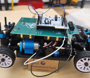
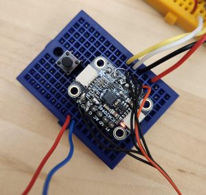
This week I completed soldering of the Glove PCB. Specifically, I soldered the finger PCB to the connector coming from the Glove PCB. This now lets us perform tests with the completed glove controller. Below is an image of the fully-soldered IMU. We are still keeping the IMU on our breadboard for testing right now.
Progress/Schedule
We are on track given our updated schedule from our interim demo. We are making good progress towards streamlining our controller and solidifying our control scheme.
Next Steps
Next week I will be working collaboratively with the rest of the team to make improvements to our control scheme and to close the loop between Kar and Kontroller.
As you’ve designed, implemented and debugged your project, what new tools or new knowledge did you find it necessary to learn to be able to accomplish these tasks? What learning strategies did you use to acquire this new knowledge?
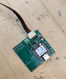
A new manufacturing technique that I had to learn was how to solder SMT components to a PCB without a stencil, and where the component pins were on the bottom of the IC. This required me to watch a YouTube video on the topic, which demonstrated a technique of mixing flux and solder paste together on the board before using a hot air gun to solder. I successfully used this technique to solder our buck converter to the Kar PCB. Additionally, I had to learn more PCB rework skills for this project, due to the manufacturing issues with our PCBs. This was mostly self-taught, as I messed around with techniques of sticking wires and components to the boards until they worked properly.