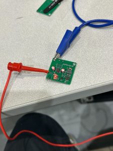
Fixed ethernet issues and now pings successfully to interface PCB. 1 of 2 illumination PCBs brought up (was delayed due to parts shipment delays) as seen in image below. Presented our work in integrating these submodules during both Monday and Wednesday interim demos.
On schedule, we aim to have the EPC660 imaging chip able to receive signals and bring up the second illumination PCB to test modulation between the two systems during this next week.
 illumination of green light
 successful pings between interface pcb and ethernet
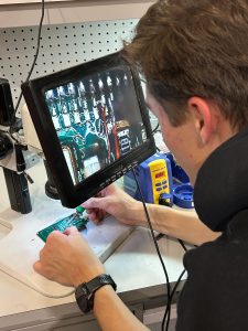
 discovering the issue with ethernet connection using xray
We also have system-level validation tests planned out for the next few weeks once the individual subsystems work well.
- Communications test: Verify that the signal chain from the image sensor all the way back to the ethernet peripheral works with <1 frame drop every minute. We will simply measure the total amount of frames and plot that versus time.
- Range test: Verify that we are able to identify a small object at 5 m of range. We define “identify” as a visually noticeable gradient in pixel shading that changes with distance. We plan on using small blocks and other objects of different shapes to fully validate this.
- Water test: Finally, we hope to put the entire enclosure underwater to verify that a) no water enters the enclosure and b) the depth maps are able to be generated of differing maps underwater. We hope to use the new RIC facility at Hazelwood Green that TartanAUV has access to for water verification.
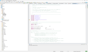
 We are on schedule, working towards the interim demo to develop firmware to get clock modulation signals working in addition to ethernet connection. Due to components shipment delay, we are focusing on getting the interface pcb subsystem working before starting on the LED driver pcbs.