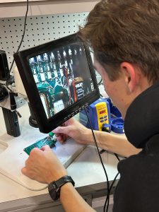
Preparations for final presentation, validating stability of modulation circuit with high side LED voltage switching cleanly, designed and ordered 2nd iteration of our smaller power board to easily perform the power up sequence necessary for the EPC600 on interface board (currently done in a tedious manner manually), DCMI alive and able to send data, much of firmware progressed this week. We are much closer to integration of our different components, and close to ready on getting system-level testing done. We have included a photo here of digital signal waveforms that show the data coming back from our image sensors.
Throughout this process, we have learned a lot about both mechanical/electrical integration, firmware nuances, and system-level design. We had to learn how to manage tradeoffs in size and power, serviceability and compactness. We also had to learn a lot more debugging skills for both hardware and software, from new types of breakpoints to PCB X-rays. We also had to do thorough design reviews and learn about the process of analog design, as well as heavy circuit theory for simulation. A lot of this knowledge came from consulting friends/colleagues who are very experienced in these areas, as we had TartanAUV alumni helping in the debugging process and design reviewing our boards.


 illumination of green light
 successful pings between interface pcb and ethernet
 discovering the issue with ethernet connection using xray
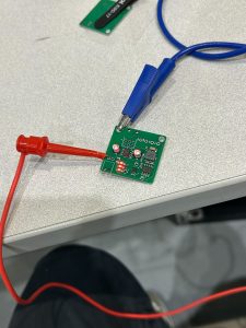 We are on schedule, working towards the interim demo to develop firmware to get clock modulation signals working in addition to ethernet connection. Due to components shipment delay, we are focusing on getting the interface pcb subsystem working before starting on the LED driver pcbs.