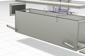
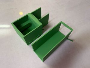
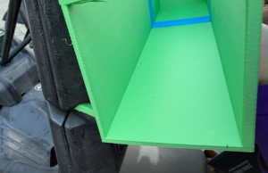
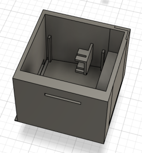
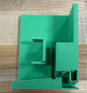
This week, I adjusted the inserts of the main Visor body to fit the basket more flush.
![]()
I also condensed the sensor cavity because the top opening just needed to accomodate the mounted sensors.
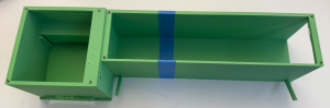
Because the sensor cavity combined with the main body was too big for the printer bed, I sliced it in half and added connectors.
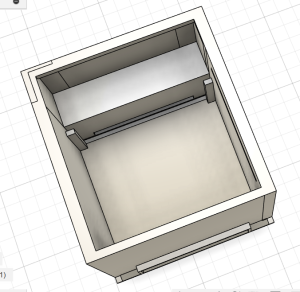
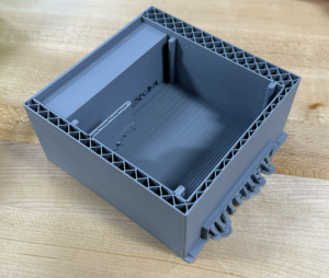
Then I printed both pieces and was able to fit both halves on the printer bed.
The prototype print was alright. The connectors weren’t a perfect fit and there was a bit of spaghetti-ing but taping the halves together was good enough for a test fitting.
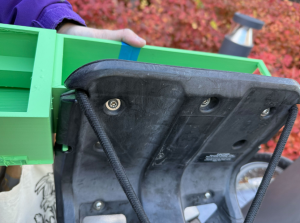
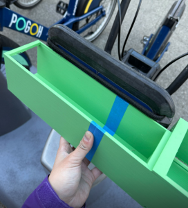
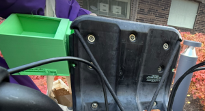
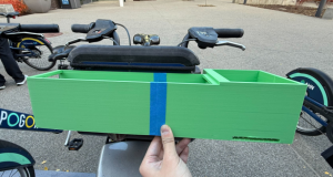
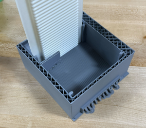
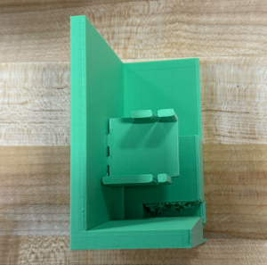
The actual fit of it on the basket was near perfect, with just a few adjustments needed.
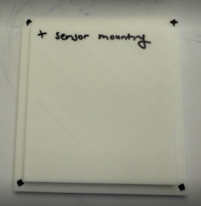
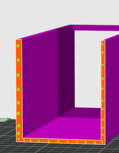
We also planned some of the heatset insert placement using the existing prototypes.
I also adjusted the rails for the next iteration because the dams were too much of a press fit.
Another huge part of the tasking this week was working on the servo mounting. I found a free 3D model of a servo ship on the internet that was for a similar servo, but importing the model into Fusion wasn’t very successful. Converting the model from mesh to body wasn’t working out and it would be a bit complicated to recreate. Thus, I searched for a simpler servo ship and discovered another free 3D model of a servo ship that was compatible with the specific servo that we have, and tried importing it into Fusion.


The model was kind of odd in that there were thousands of polygons so it was causing my computer to lag, especially when I was trying to adapt it for use. Thus, I ended up just recreating the parts that I needed instead, so that it would be easier to adapt for our purposes.
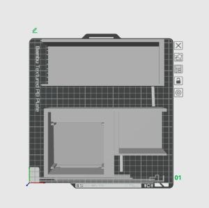
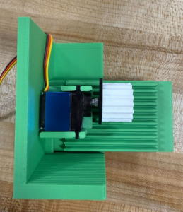
I tried attaching it to the sensor cavity and then setting it to print so we could see the fit of it and check the measurements.
The printer ran out of filament in the middle, but this was actually fortunate because it printed just enough for us to get a lot of good information out of it. For example, I found that the printer struggled to create supports for the servo ship, so I decided to print that separately (with a plug connector) for the next iteration. It was also enough to check and adjust the rail dimensions.
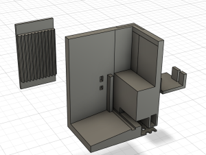
For the next iteration, I made a small slice of the cavity and also printed the servo ship along with it, as well as an adjusted air dam.
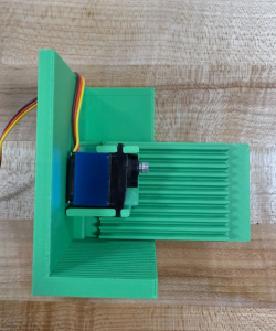
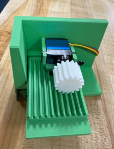
The fit of this iteration was near perfect if not perfect. The servo fits well into the servo ship, the distance of the gear and the fit of it with the dam was very good as well. I will be adding the second servo ship plug connections to the model next week.
I am a bit behind schedule but with the servo mounting mostly complete, we have made significant progress on one of the most critical parts of our project.
Next week, I will continue working on the servo ships, look again into the heatset inserts for testing, and work on the combined body of the Visor, including the battery cavity.
0 Comments