This past week, I worked on designing, modeling, and constructing the air dam prototypes. 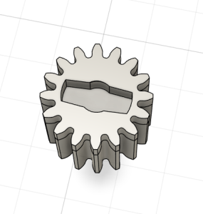
The designing took a bit of time because while we were adapting an existing 3d model for the rack and pinion system, we needed to keep a few things in mind. The servos have a maximum of 180 degrees of rotation, meaning that 180 degrees of gear rotation must have enough vertical distance covered to fully open and close the intake and exhaust apertures. The two apertures have different dimensions, so it would be best if the air dam system can accomodate both. Second, neither the retailer nor the direct supplier of the servos had exact dimensions for the servo gear/arm with splines, nor had a listing for or specification for the servo horns that are compatible with the servos that we have. Because of this, we needed a design that allows the servo horns to be reused for every iteration of the prototype. Thus, we designed a gear with an insert for the servo horn to increase grip and allow for testing without destruction with every prototype.
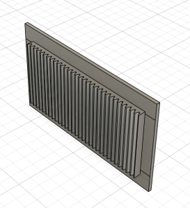
I also extended the rack to decrease the chance of the gear slipping off, but we are considering a more inset rack system so that the gear has no room to shift.

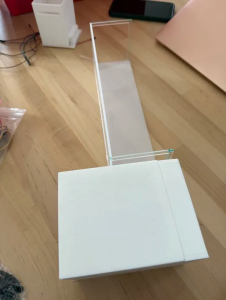
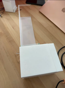
This week I also printed these parts out so that we can test the fit and effectiveness of the mechanism, as well as test for space and layout within the sensor cavity.
In addition to this, the team and I discussed the orientation of the sensor pod of the visor with relation to the main body.
My progress is still slightly behind schedule. The sensor cavity is my main focus at the moment because that is where most of the activity and movement occurs, but I will need to start pulling everything together soon for a first iteration of the entire Visor.
In the coming week, I plan to work on accomodation for the heatset inserts, creating rails for the air dam, and adjusting the basket inserts on the 3d model of the Visor main body.
0 Comments