This week, I finished a second iteration of the Visor’s sensor cavity and main body 3D models. For the sensor cavity, I included the outer casing for the intake, expanded the size to accomodate the sensors since the first iteration was too small, and started working on creating lids. For the main body, we decided that the opening for the main body should also be on top, so I filled in the front wall and created a lid.


For sensor cavity Ver.2, there were enough changes that we printed this iteration for testing. The following images are the sliced file and photos we took after the print finished.


The print was much larger than before, and the material was sturdier than we thought it would be. Because it is very large, I ended up compressing the box 3D model at the end of the week so that it would be a bit more compact and less unwieldy.

For the main body, I made another lasercut acrylic prototype so we could test the fit of the inserts again.
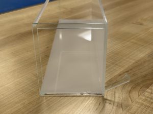


This version fit the basket much better. It rested flush against the front of the basket, was just short enough vertically to allow for basket loop clearance, and the angle of the inserts was perfect.


As for the air dams, our team had a lot of discussion this week about how we wanted to go about their specific design. The servos only come with a finite number of servo horns and neither Adafruit or the company the servo was produced by have dimensions or indicators of what the dimensions of the servo’s external gear is (other than spline number) or what variation of servo horn. I ended up finding someone’s replacement servo horn 3D model online, importing it into Fusion. I intend to measure the servo horns and compare with the 3D model’s measurements, and plan to use it as a reference for servo horn attachments.


I also found a rack and pinion 3D model that we plan to apply to our air dam.

I have also talked with Cody Soska and our group now has access to heatset inserts that we plan to use for sensor mounting and lid closure.
My progress is still a bit behind. I decided to prioritize the actual sensor cavity and main body first as those still needed to be adjusted, and a second iteration of the cavity that would actually fit the sensors would be much better to test with. While I haven’t solidified the design and dimensions of the air dams yet, our team has discussed and decided the orientation of the rack and pinion system with respect to the air dams. I was also able to an existing rack and pinion system model for use, with some trouble importing it into Fusion for modification. With this, I should be able to just adjust the size and dimensions using the existing model as a base, and then create a first iteration of the air dams.
Next week, I will be adjusting the main body 3D model by bringing the inserts inwards horizontally and extending the insert length. I will also start working on the air dam system, making a modified gear that will be able to bracket the existing servo horn and attaching the rack to a dam door. I also hope to get measurements of the heatset inserts so that I can adjust the 3D models making up the Visor to be compatible with them.
0 Comments