Mahlet’s Status Report for 12/07/2024

This week, mainly consisted of debugging my audio localization solution and making necessary changes to the hardware of SBB. 

Hardware

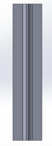
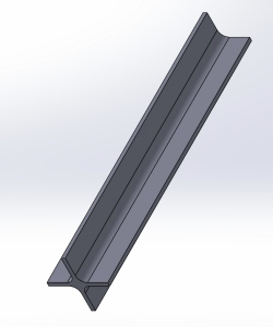
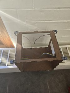
Based on the decision to change motors from servo to stepper, I had to change the mounting mechanism of the robot’s head to the body. I was able to reuse  most of the components from the previous version, and had to make the mounting stand slightly longer to be in line with our use case requirement. Now the robot can move its head very smoothly and consistently. 

My work on audio localization and its integration with the neck rotation mechanism has made significant progress, though some persistent challenges remain. Below is a detailed breakdown of my findings and ongoing efforts.

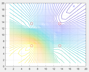
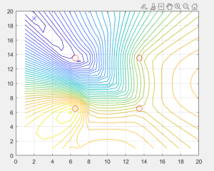
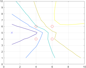
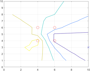
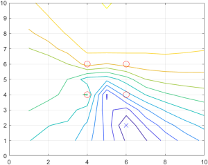
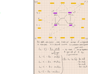
To evaluate the performance of the audio localization algorithm, I conducted simulations using a range of true source angles from 0° to 180°. The algorithm produced estimated angles that closely align with expectations, achieving a mean absolute error (MAE) of 2.00°. This MAE was calculated by comparing the true angles with the estimated angles and provides a clear measure of the algorithm’s accuracy. The result confirms that the algorithm performs well within the intended target of a ±5° margin of error.

To measure computational efficiency, I used Python’s time library to record the start and end times for the algorithm’s execution. Based on these measurements, the average computation time for a single audio cue is 0.0137 seconds. This speed demonstrates the algorithm’s capability to meet real-time processing requirements.

In integrating audio localization with the neck rotation mechanism, I observed both promising results and challenges that need to be addressed.

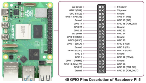
For audio cue detection, I tested the microphones to identify claps as valid signals. These signals were successfully detected when they exceeded an Arduino ADC threshold of 600. Upon detection, these cues are transmitted to the Raspberry Pi (RPi) for angle computation. However, the integration process revealed inconsistencies in serial communication between the RPi and the Arduino.

While the typical serial communication latency is 0.2 seconds or less, occasional delays ranging from 20 to 35 seconds have been observed. These delays disrupt the system’s responsiveness and make it challenging to collect reliable data. The root cause could be the Arduino’s continuous serial write operation, which conflicts with its role in receiving data from the RPi. The data received on the RPi seems to be handled okay, but I will proceed to validate the data side-by-side, and make sure the values are accurate.  Attempts to visualize the data on the computer side were too slow for the sampling rate of 44kHz, leaving gaps in real-time analysis.

To address hardware limitations, I have temporarily transitioned testing to a laptop due to USB port issues with the RPi. However, this workaround has not resolved the latency issue entirely.

Despite these challenges, the stepper motor has performed within expectations. The motor’s rotation from 0° to 180° was measured at 0.95 seconds, which meets the target of under 3 seconds, assuming typical latency.

Progress is slightly behind schedule, and the contingency plan for this is indicated in the google sheets of the team weekly report.

Next Steps

Resolving the serial communication latency is my highest priority. I will focus on optimizing the serial read and write operations on both the Arduino and RPi to prevent delays. Addressing the RPi’s USB port malfunction is another critical task, as it will enable me to move testing back to the intended hardware. Otherwise, I will resort to the contingency plan of using the webapp to compute the data. I will be finalizing all the tests I need for the report, and finalize integration with my team over the final week.

Mahlet’s Status Report for 11/30/2024

As we approach the final presentation of our project, my main focus has been preparing for the presentation, as I will be presenting the coming week. 

In addition to this, I have assembled the robot’s body, and made necessary modifications to the body to make sure every component is placed correctly. Below are a few pictures of the changes so far. 

I have modified the robot’s face so that it can encase the display screen. Previously, the head was a solid box. The servo to head mount is now properly assembled. The head is well balanced using the stand I used to mount the motor to. This way there is space to place the Arduino, speaker and RaspberryPi accordingly. I have also mounted the microphones to the corners as desired. 

Before picture: 

After picture: 

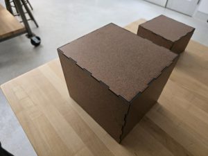
Mounted microphones on to the robot’s body

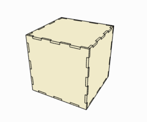
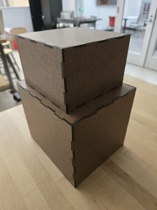
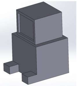
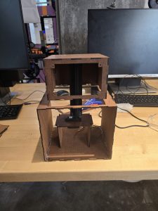
Assembled Body of the robot

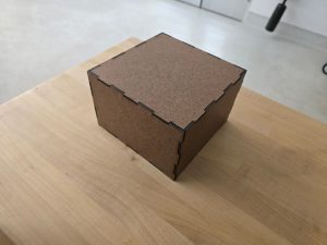
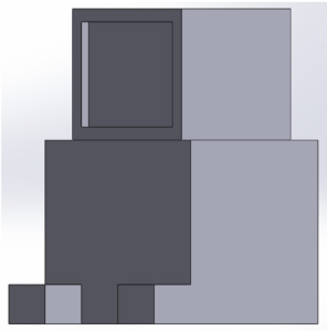
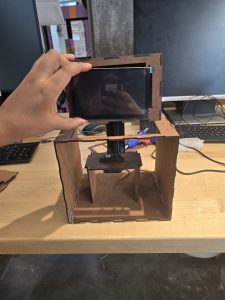
Assembled body of the robot including the display screen


I have been able to detect a clap cue using the microphone, by identifying the threshold of a loud enough clap detectable by the microphone. I do this processing in the raspberry pi, and once the RPi detects the clap, it runs the signal through the direction estimate function, which spits out the angle. This angle is then sent to the Arduino to modify the motor to turn the robot’s head. Due to the late arrival of our motor parts, I haven’t been able to test the integration of the motor with the audio input.  This put me a little behind, but using the slack time we allocated, I plan to finalize this portion of the project within the coming week.

Another thing I worked on is implementing the software aspect of the RPS game, and once the keypad inputs are appropriately detected, I will meet with Jeffrey to integrate these two functionalities. 

I briefly worked with Shannon to make sure the audio output for the TTS through the speaker attached to the RPi works properly. 


Next week: 

  1. Finalize the integration and testing of audio detection + motor rotation
  2. Finalize the RPS game with keypad inputs by meeting with the team. 
  3. Finalize the overall integration of our system with the team. 

Some new things I learned during this capstone project is how to use serial communication between Arduino and a raspberry pi. I used some online Arduino resources that clearly teach how to do this. I also learned how to perform signal analysis on audio inputs to localize the source of a sound within a range. I learned how to use the concept of time difference of arrival to get my system working. I used some online resources about signal processing, and by discussed with my professors to clarify any misunderstandings I had towards my approach. I also learned from online resources, Shannon and Jeffrey how a WebSocket works. Even though my focus was not really on the web app to RPi communication, it was good learning how their systems work.

Mahlet’s Status Report for 11/16/2024

This week, I was able to successfully finalize the audio localization mechanism. 

Using matlab, I have been able to successfully pinpoint the source of an audio cue with an error margin of 5 degrees. This is also successful for our intended range of 0.9 meters,  or 3 feet. This is tested using generated audio signals in simulation. The next step for the audio localization is to integrate it with the microphone inputs. I take in an audio input signal and pass it in through a bandpass to isolate the audio cue we are responding to. The microphone then keeps track of the audio signals, in each microphone for the past 1.5 seconds, and uses the estimation mechanism to pinpoint the audio source. 

In addition to this, I have 3D printed the mount design that connects the servo motor to the head of the robot. This will allow for a seamless rotation of the robot head, based on the input detected. 

Another key accomplishment this week is the servo motor testing. I ran into some problems with our RPi’s compatibility with the recommended libraries. I have tested the servo on a few angles, and have been able to get some movement, but the calculations based on the PWM are slightly inaccurate.

The main steps for servo and audio neck accuracy verification is as follows. 

Verification 

The audio localization testing on simulation has been conducted by generating signals in matlab. The function was able to accurately identify the audio cue’s direction. The next testing will be conducted on the microphone inputs. This testing will go as follows: 

  1. In a quiet setting, clap twice within a 3 feet radius from the center of the robot. 
  2. Take in the clap audio and isolate ambient noise through the bandpass filter. Measure this on a waveform viewer to verify the accuracy of the bandpass filter. 
  3. Once the clap audio is isolated, make sure correct signals are being passed into each microphone using a waveform viewer. 
  4. Get the time it takes for this waveform to be correctly recorded, and save the signal to estimate direction.
  5. Use the estimate direction function to identify the angle of the input. 

To test the servo motors, varying angle values in the range of 0 and 180 will be applied. Due to the recent constraint of neck motion of the robot, if the audio cue’s angle is in the range of 180 and 270, the robot will turn to 180. If the angle is in the range of 270 and 360, the robot will turn to 0. 

  1. To verify the servo’s position accuracy, we will use an oscilloscope to verify the servo’s PWM, and ensure proportional change of position relative to time. 
  2. This will also be verified using visual indicators, to ensure reasonable accuracy. 

Once the servo position has been verified, the final step would be to connect the output of the estimate_direction to the servo’s input_angle function. 

My goal for next week is to:

  1. Accurately calculate the servo position
  2. Perform testing on the microphones per the verification methods mentioned above
  3. Translate the matlab code to python for the audio localization
  4. Begin final SBB body integrating


Mahlet’s Status Report 11/09/2024

This week, I worked on Audio localization mechanism, servo initialization through the RPi and ways of mounting the servo to the robot head for seamless rotation of the head. 

Audio localization: 

I have a script that records audio for a specified duration, in our case would be every 1.5 seconds, and this will take in an input audio and filter out the clap sound from the surrounding using a bandpass filter. This audio input from each mic is then passed into the function that performs the direction estimation by performing cross correlation between each microphone. 

I have finalized the mathematical approach using the four microphones. After calculating the time difference of arrival between each microphone, I have been able to get close to the actual input arrival differences with slight variations. These are causing very unstable direction estimation to a margin of error to up to 30 degrees. The coming week, I will be working on cleaning up this error to ensure a smaller margin of error, and a more stable output. 

I also did some testing by using only three of the microphones in the orientation (0,0), (0, x), (y, 0) as an alternative approach. x and y are the dimensions of the robot(x = 8 cm, y = 7cm). This yields slightly more inaccurate results. I will be working on fine-tuning the 4 microphones, and as needed, I will modify the microphone positions to get the most optimal audio localization result.

Servo and the RPi: 

The Raspberry pi has a built-in library called python3-rpi.gpio, which initializes all the GPIO pins on the raspberry pi. The servo motor connects to the power, ground and a GPIO pin which receives the signal. The signal wire connects to a PWM GPIO pin, to allow for precise control over the signal that is sent to the servo. This pin can be plugged into GPIO12 or GPIO13. 

After this, I specify that the pin is an output and then initialize the pin. I use the set_servo_pulsewidth function to set the pulse width of the servo based on the angle from the audio localization output. 

Robot Neck to servo mounting solution: 

I designed a bar to mount the robot’s head to the servo motor while it’s housed in the robot’s body. 

The CAD for this design is as follows.

By next week, I plan to debug the audio triangulation and minimize the margin of error. I will also 3D print the mount and integrate it with the robot, and begin integration testing of these systems.


Mahlet’s Status Report for 11/02/2024

This week, I worked on the robot base structure building. Based on the CAD drawing we did earlier in the semester, I generated parts for the robot base and head that have finger edge joints. This allows for easy assembly. This way we can disassemble the box to modify the parts on the inside, and easily reassemble it back. The box looks as follows: 

During this process, I used the 1/8th inch hardwood boards we purchased and cut out every part of the body. The head and the body are separate, as they will be connected with a rod to allow for easy rotation and translational motion. This rod will be mounted to the servo motor.  As a reminder, the CAD drawing looks as follows.  

I laser cut the boxes and assembled each part separately. Inside of the box, we will be placing the motors, RPi, and speakers. The wiring of the buttons will also be placed in the body of the robot. The  results are as follows. The “feet” of the robot will be key inputs, which haven’t been delivered yet. The result so far look as follows: 


In addition to these, I worked on the TTS functionality with Shannon. I did some tests and found that the Pyttsx3 library works when running text input iterations outside of the webapp. The functionality we are testing is integrating the text input directly into the text to speech engine. This kept causing the loop error. When I tested the pyttsx3 in a separate file where I pass in various texts back to back by only initializing the engine once, it works as expected. 

We also worked on the gTTS library. The way this works is, it generates an MP3 file for the text file input and then reads that out once it’s done. This file generation causes a very high latency. For a thousand words, it takes over 30 seconds to generate the file. Despite this, we came up with plans to break up the file into multiple chunks and create the MP3 files in parallel, lowering the latency. This would get us to a faster TTS time, without having any issues similar to the pyttsx3 library. This is a better and fully functional alternative from our options, with a reasonable tradeoff of having slightly longer latency for longer texts for a reliable TTS machine.

In the coming week, I will be working mainly on finalizing the audio triangulation along with some testing, and begin integrating systems the servo system with the audio response with Jeffrey.

Mahlet’s Status Report for 10/26/2024

This week I worked on the forward audio triangulation method with the real life scale in mind. I limited the bounds of the audio source to 5 feet from each side of the robot’s base and placed the microphones at a closer distance. I accounted for accurate values in units to make my approximation possible. Using this, and knowing the sound source location, I was able to pinpoint the source of the audio cue. I used a smaller scale to go over the grid dimensions to have a closer approximation. This is to allow low inaccuracies in the direction that the robot is going to turn to. 

I randomly generate the audio source location, and below are some of the simulations for this.  The red circles denote the source of audio and the cross indicates the audio source.

After this,  I pivoted from audio triangulation and focused on tasks such as setting up the RaspberryPi, doing tests for the TTS with Shannon and learned  about the WebSocket connection methodology. I joined Shannon and Jeffrey’s session when they discussed the WebSocket’s approach and learned about it

During setting up the RaspberryPi, I ran into some issues with it, while trying to SSH to it. Setting up folders and the basics however went well. One task for next week is to reach out to the department to get more information about prior connections with the raspberry pi. It is already connected to CMU Secure as well as CMU devices networks, however it doesn’t seem to be working with the CMU device network. I tried registering the device to CMU Devices, but it seems like it has been registered prior to this semester. I aim to figure out the issue with SSH-ing to this device over the next week. However, we can still work with the RPi using a monitor, so this is not a big issue. 

After this, I worked on Text-To-Speech along with Shannon, and worked on the pyttsx3 library. We intended so that the WebApp reads various texts back to back through the text/file input mechanism. The library works by initializing a text engine, and uses the function, engine.say(), to read the text input. This works when running the app for the first time. However after inputting data for the second time and onwards, it gets stuck in a loop. The built-in engine.stop() function requires multiple instances of initialization of the text engine, which causes the WebApp to lag. As a result, Shannon and I have decided to look into more TTS libraries that can be used for python, and also we will try testing the TTS directly on the RPi instead of the WebApp first.

My progress is on track, the only setback is the late arrival of ordered parts. As described in the team weekly report, I will be using the slack time to accommodate for progress with assembling the robot, and integrating systems. 

Next week I will be working on finalizing the audio triangulation, work with Shannon to find the optimal TTS functionality and work with Jeffrey to build the hardware.

Mahlet’s Status Report for 10/12/2024

This week, I focused mainly on the design report aspect. After my team and I had a meeting, we split up the different sections of the report fairly, and proceeded to work on the deliverables. 

I worked mainly on the audio triangulation, robot neck motion(components included) and the robot base design. In the design report, I worked on the use-case requirements of the audio response and the robot base. I made the final block diagram for our project. After this, I worked on the design requirements for the robot’s dimensions, and the audio cue response mechanism. After identifying these, I worked on the essential tradeoffs for choosing to use some of our components such as the Raspberry Pi, the servo response, choice of material for our robot’s body, and microphone for audio input. After this, I worked on the system implementation for the audio cue response and unit and integration testing of all these components. 

Following our discussion, I finalized the bill of materials, and provided risk mitigation plans for our systems and components. 

In addition to this, I was able to spend some time discussing the audio response methodology and approach with Professor Bain. After implementing the forward audio detection system (i.e. knowing the location of the audio source and the location of the microphone receivers), my goal was to work backwards, without knowing the location of the audio source. From this meeting, and further research, I concluded my approach as follows, and will be working on it in the coming week. More detail on this implementation can be found on the design report.

The system detects a double clap by continuously recording and analyzing audio from each microphone in 1.5-second segments. It focuses on a 1-second window, dividing it into two halves and performing a correlation to identify two distinct claps with similar intensities. A bandpass filter (2.2 kHz to 2.8 kHz) is applied to eliminate background noise, and audio is processed in 100ms intervals.

Once a double clap is detected, the system calculates the time difference of arrival (TDOA) between microphones using cross-correlation. With four microphones, it computes six time differences to triangulate the sound direction. The detection range is limited to 3 feet, ensuring the robot only responds to nearby sounds. The microphones are synchronized through a shared clock, enabling accurate TDOA calculations, allowing the robot to turn its head toward the detected clap.

I am a little behind on schedule as parts are not here yet. I will be working on the Robot base building with Jeffrey once that is complete, and do testing on the audio triangulation with microphones and RPi after performing the necessary preparations within the coming week. 

Mahlet’s Status Report for 10/05/2024

This week, my primary focus was gathering data for the design report and completing tasks related to audio localization.

For the audio localization, I used MATLAB to simulate and pinpoint an audio source on a randomly generated 10×10 grid. I arranged the microphones in a square (2×2) configuration and randomized the location of the audio source. By calculating the distance between each microphone and the audio source, and considering the speed of sound (approximately 343 m/s), I determined the time delays relative to each microphone.

I applied the Time Difference of Arrival (TDOA) method. For each pair of microphones, the difference in the time it takes for sound to reach each microphone forms a hyperboloid. I repeated this process for every microphone pair, and the intersection of these hyperboloids provided a reasonable estimate of the audio source’s location. In MATLAB, I looped over the grid and computed the integer intersections of various locations. Using the Euclidean approach, I predicted the distance and calculated the corresponding TDOA using the speed of sound. By comparing the predicted TDOA with the actual time delays, I tried to estimate the error in the localization process.

The following figure illustrates the results, where ‘X’ represents the audio source, and ‘O’ marks the microphone positions. Additionally, I will include the relevant equations that informed this approach.


Currently, I am facing an issue with pinpointing the exact location of the source. To address this, I plan to refine the grid resolution by using smaller iterations, which should allow for greater accuracy. I will also calculate and display the approximate error in the final results. So far, I have a general idea of the audio source’s location, as indicated by a dark blue line, and I will continue working to pinpoint the exact position. Once I achieve this, I will conduct further simulations and eventually test the system using physical microphones, which will introduce additional challenges.

I am slightly behind on the project schedule. By next week I aim to finalize the audio localization section of the design report, along with the remaining parts of the report, in collaboration with my team.  I had a goal to setup the robot neck rotation servos by this week. This hasn’t been done as well. We will be finalizing the bill of materials by this week. I will be working on this as early as the components get in. To make up for this, I will be spending some time over fall break working on this.

According to the Gantt chart, Jeffrey and I had planned on building the robot, by the end of this week. This hasn’t been completed yet, but the CAD design is already completed. This week we will meet and discuss more about space constraints and make decisions accordingly.

Mahlet’s Status Report for 9/28/2024

This week, I worked on the CAD design of our Studybuddy robot using Solidworks. After discussing with my team about the space constraints and objects we will need to integrate in the robot, we decided on general dimensions that give optimal dimensions. The base box is 8in x 7in x 6in. The head is 6in x 6in x 5in. The DCI display screen will be attached to the head in the designated extrusion as shown in the CAD drawing. The legs will contain buttons to power on the robot, pause and continue timers if necessary and buttons to interactively play rock paper scissors. Output of the buttons will be displayed on the DCI display from both players.

Considering the fact that the directional microphones are not reliable to pinpoint the exact direction of sound, I would have to start by creating simulations to see how the audio is delivered at different corners of the robot. I am still planning to use a combination of the MEMS array of microphones along with the directional microphones. Following the previous week’s feedback and finalized the microphones and will start creating simulation models to conceptualize the system behavior. 

 I am on track with the progress for this week. I have identified the microphones and servo motors we will be using for the robot. In addition, I have borrowed (free) a photoresistor, an ultrasonic sensor, and a temperature and humidity sensor for testing purposes. 

By next week, I would like to get more research regarding the audio triangulation mechanism and mathematical derivation. I will be setting up the text-to-speech libraries on a computer and figure out the integration with RaspberryPi, and setting up speakers from the RPi by week 7 with Shannon. I will also meet with Jeffrey to analyze motor specifications including the voltage, power and torque using datasheets. 

Mahlet’s Status Report for 9/21/2024

This week, I worked on some of the feedback we got from the proposal presentation regarding the audio triangulation, the robot motion, choices of microphones, and justification for using 3 microphones. According to my research, I can justify the use of three microphones by indicating that it allows for 2D audio recognition, when paired with a directional microphone. The three microphones are going to be MEMS microphones. The triangulation technique requires very accurate time measurements and using MEMS might introduce some timing delays affecting the precision of audio. However, since a directional microphone can give us a sense of the general origin of an audio, using the signals coming through both of these and aligning and processing them will help us get a more precise audio output with an aim of 5 degree of margin of error.

In light of the proposal update, I have made slight modifications to my goals within the next few weeks on the Gantt chart. I will be working on identifying specific components for the purposes mentioned above, and I swapped the deadline for the robot neck logic and the triangulation math, based on priority. I am on track based on the Gantt chart.

During next week, I will be working on identifying good directional microphones to integrate with the MEMS microphone to have good results, and identifying the motion motors for the neck of the robot. I will also do more research on allowing audio triggers within a certain length radius from the robot. Once I identify the servos I will be using, I will work on the audio triangulation method. I will be working on the bill of materials(BOM) with my team to finalize the parts list.