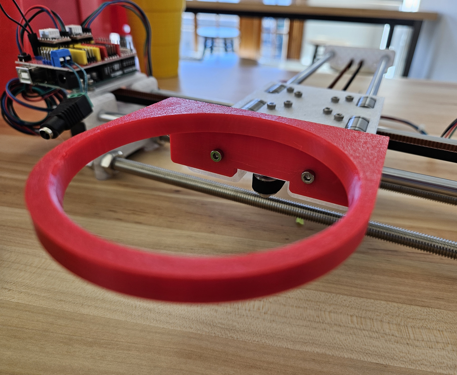
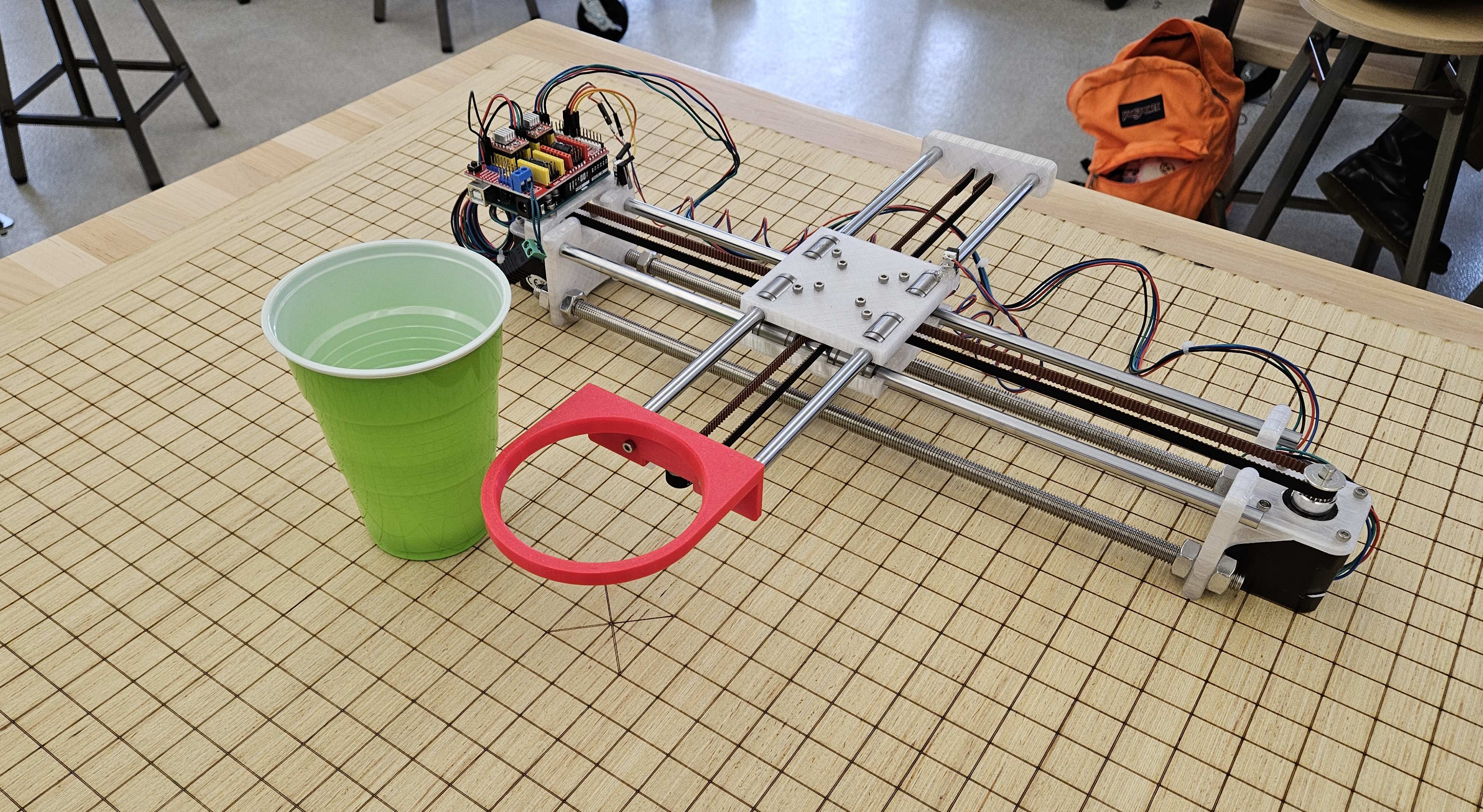
Josiah’s Status Report for 12/7

Accomplishments

The final report… at this point, we’re laser focused on integrated everything. Besides the robot and finalizing the demonstration setup (the wood base-board warped due to being so thin… tape everywhere!), I whipped up a metrics visualization script that plots shots made onto a graph. It differentiates between shots outside of the robot’s catching area, shots made inside the square area, and shots made in the cup without needing assistance (a splash!). This was accomplished through matplotlib. I need to add a bit more to show accuracy, shots made percentage over a total session, and I think it would be cool to include a color map based on how far the shot is away from (0,0). But it’s mostly complete.

Progress

I’ve additionally been helping Jimmy with integrating the robot with the camera + Kalman operation. Next is shifting gears to churning out the poster and video.

Team Status Report for 11/30

Status Report for 11/30

As each of our individual portions began to conclude, we started to focus on the integration of the project. Check Gordon’s individual status report for more details on 3D coordinate generation. Since Gordon is in charge of most of the hardware integration section, I took charge in drawing out what the real world mapping would look like, and did a calibration test to see how many pixels on the camera frame was equivalent to how many centimeters in real life. Below is a picture of how our mapping is visualized and connected between the Camera/RPI and the XY robot.

For the code that would integrate it all, I worked with Jimmy to create “main” function files that would tie together code to operate the 2D and 3D cameras, detection, kalman filter, and G-code interface. This is our final pipeline, and we were able to get it to a point where all we needed was to physically align and calibrate the camera in real life, and could begin our testing of the project from camera to robot. We actually made 2 “main” files, one for a simpler 2D pipeline (this would not have the depth camera activated) and one for the whole 3D one, since I was still fine tuning the 3D detection and coordinate generation while Jimmy created the 2D pipeline code. We are planning to first test the 2D pipeline, as switching to 3D will be as easy as running a different file. 

On the camera and prediction side for Jimmy, all implementation details have been completed. The 3D kalman filter was completed, however testing needs to be done to verify the correctness using real world coordinate systems, for tuning for acceleration variables. Some roadblocks that was run into included the producer/consumer problem between threads when using multithreading to increase the camera FPS, which was eventually resolved. Currently, the biggest unknown and risk for our project remains to be the integration, which we will be working tirelessly for until demo day. Jimmy will be focusing mostly on the software integration of the camera detection, tracking, prediction on the raspberry pi. The following video is a real-time capture of the detection, and kalman prediction being done in real-time for a ball being thrown (more details in individual report)

On the robotics side, everything is complete. See Josiah’s status report for detailed documentation on what was accomplished. The big points are that serial communication through a python script is functional with the firmware running on the Ardunio (use a simple USB cable), and it’s possible to queue multiple translation commands to grbl because it has an RX buffer. Therefore, it integrates well with the Kalman Filter’s operation, as it generates incrementally better predictions iteratively. These can be passed to the robot as updates are made.

Josiah’s Status Report for 11/30

Accomplishments

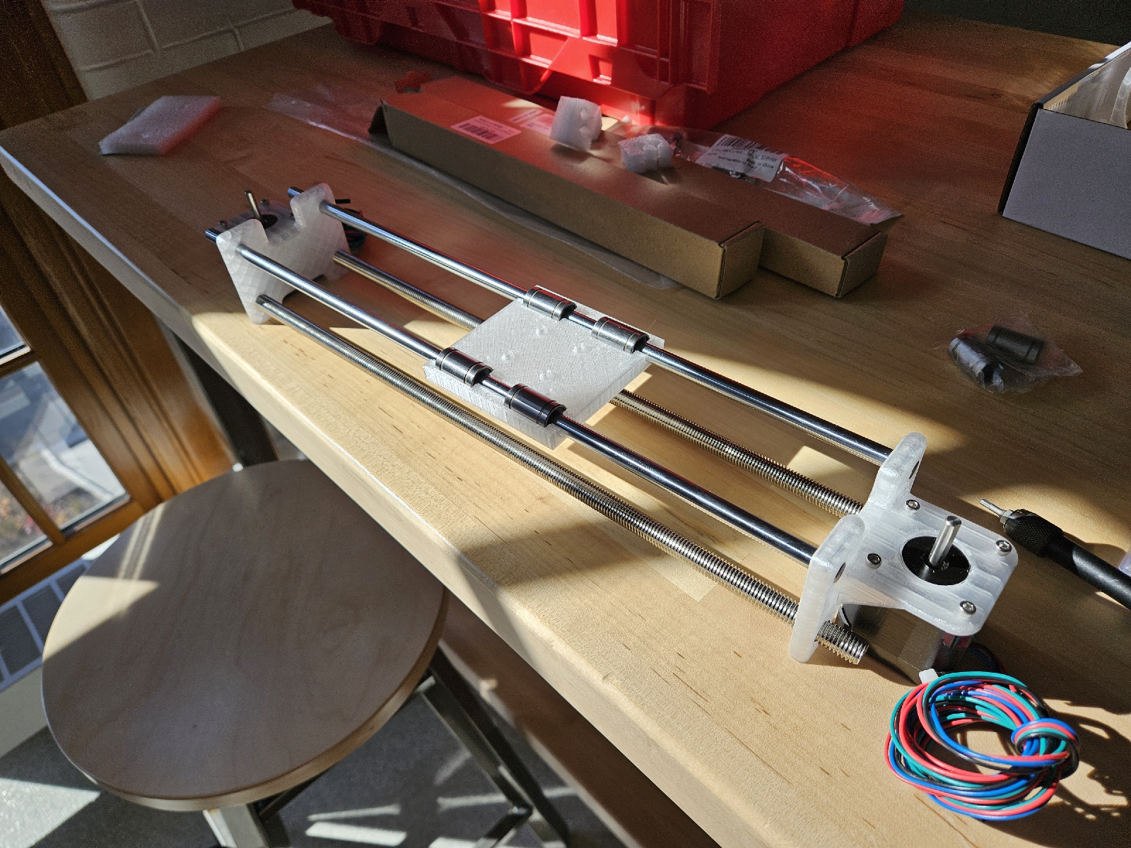
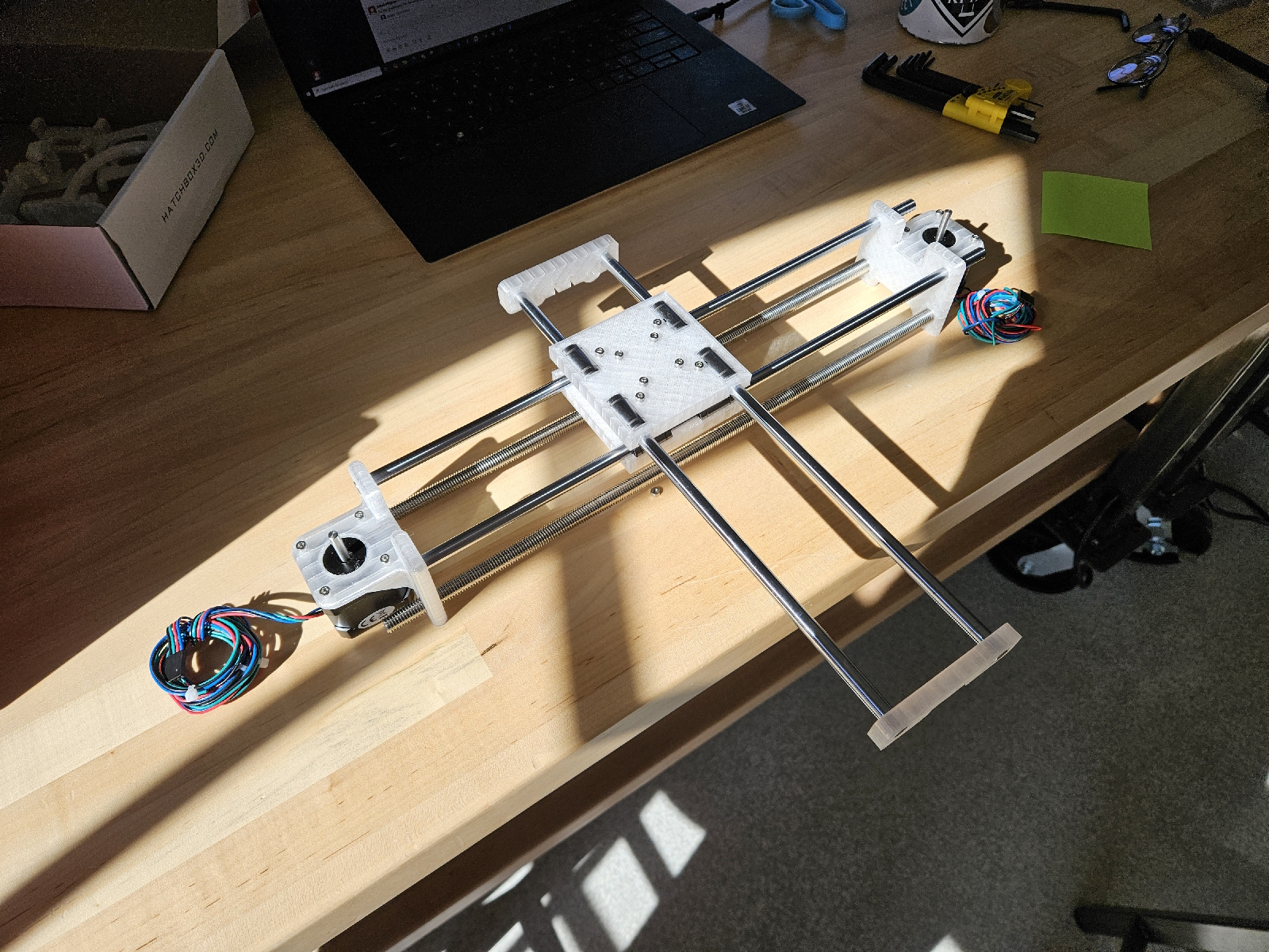
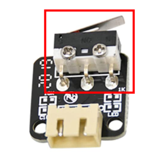
In short, the robot really is complete! It was mainly finishing touches. Instead of purchasing new limit switches, I just snipped the actual switch from the end stop that was intended for a 3d printer. From there, a little bit of soldering, wiring and glueing completed my homing setup. From now on, the origin will always be well defined and replicable, and therefore all translations well defined and replicable. I only used two limit switches, so hard limits aren’t quite enforced on the +X and +Z axis… but ideally we never exceed 10cm in any direction with software-enforced checks.

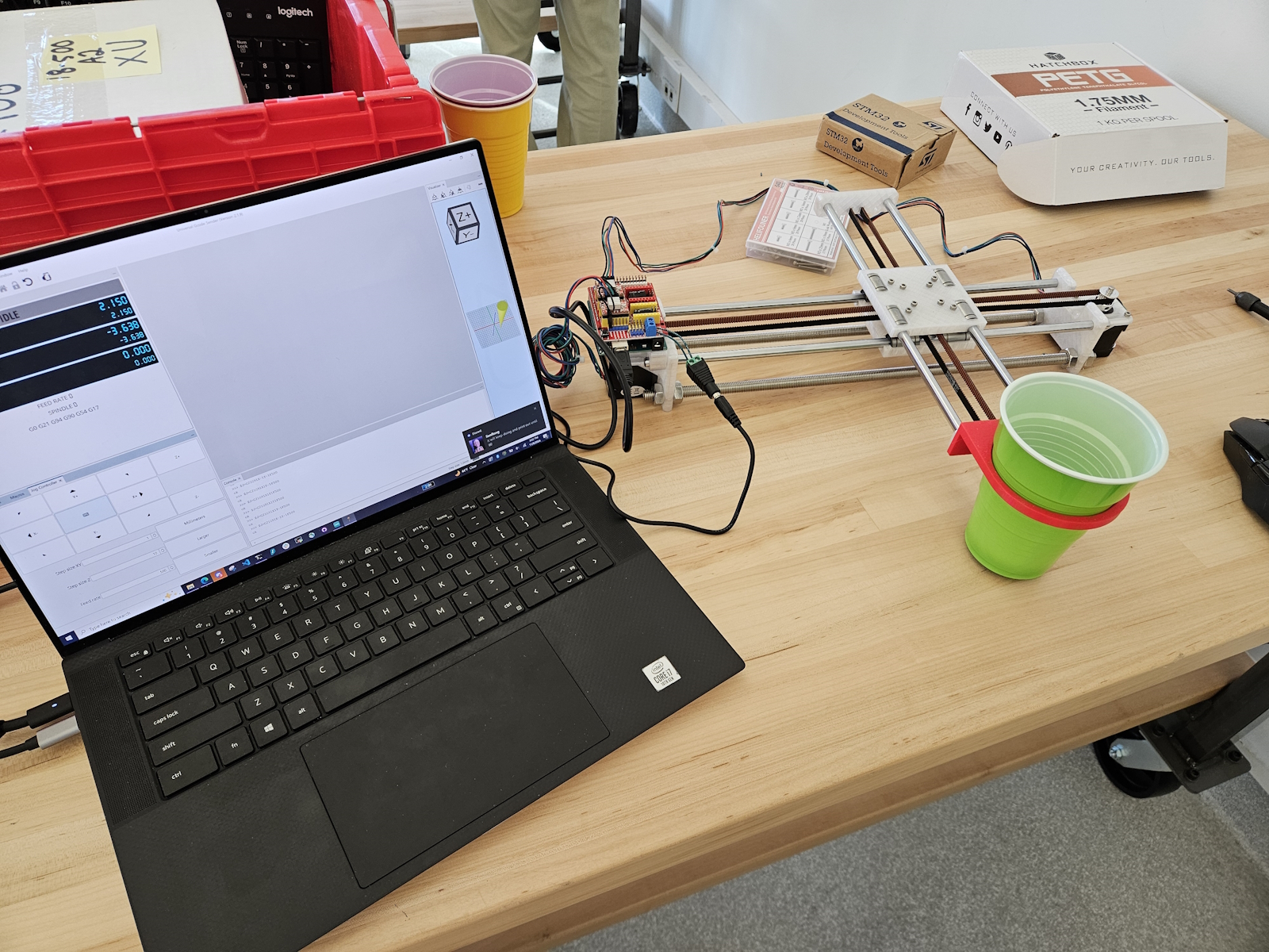
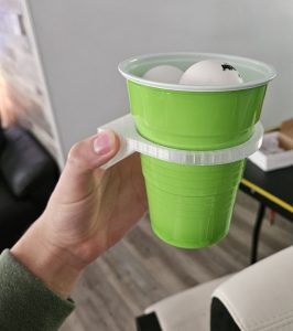
I’ve successfully migrated away from UGS and have implemented serial communication with the Arduino running the firmware through a python script. This will integrate cleanly with the rest of the system (RBP, camera). All integration requires on the side of the Pi is to first establish a connection over serial (USB) with the grbl firmware, and initialize some processes and configs, namely homing, feed rate, among others. Then whenever a prediction is made, simply call gcode_goto(x, y) to move the cup.

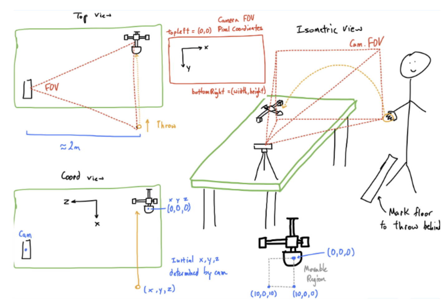
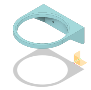
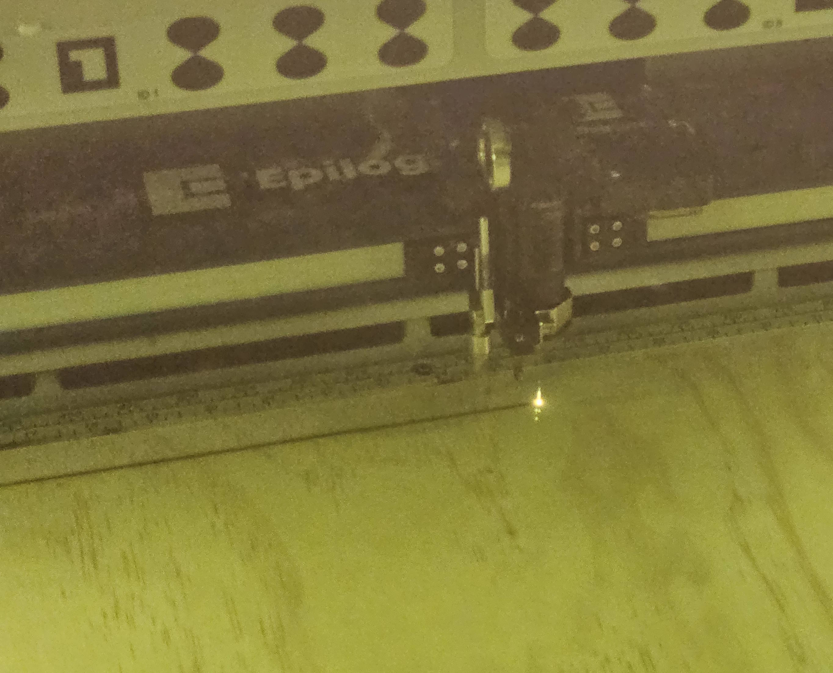
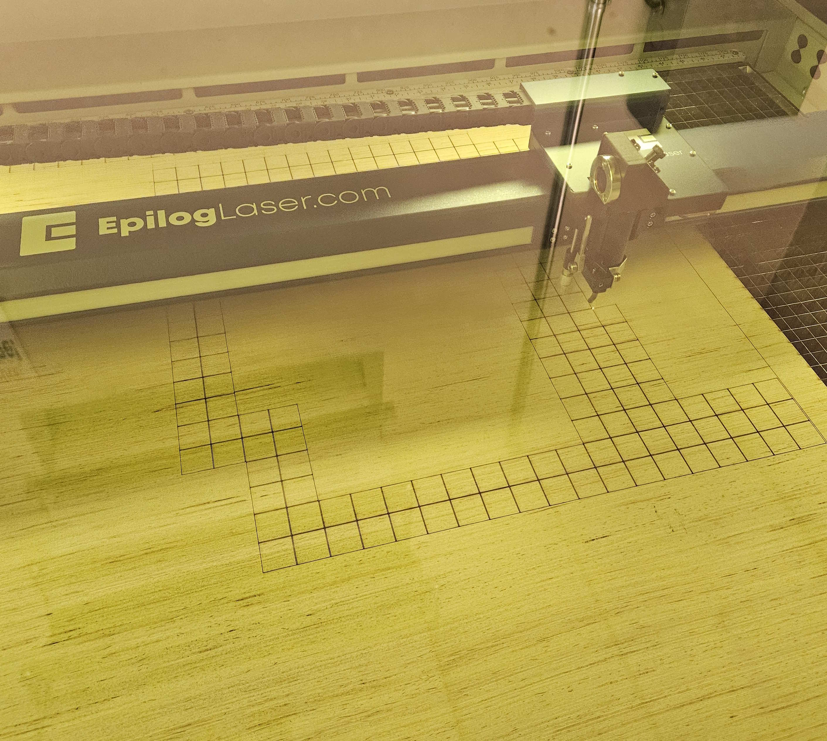
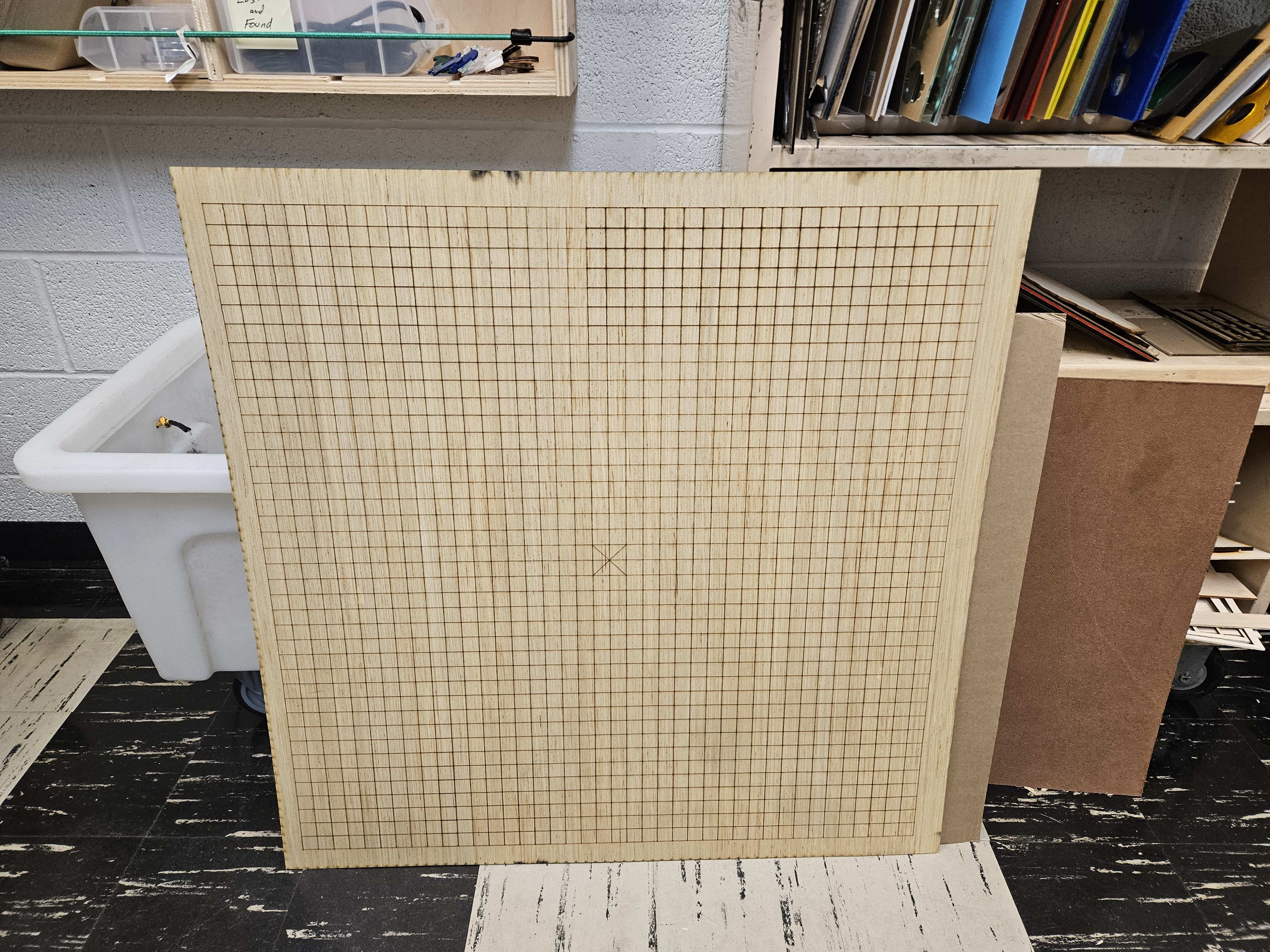
To add to this, I verified the robotics system. A maximum translation of 10cm takes at most 0.4s, which provides ample time. Secondly, I determined that grbl has a receiving buffer. In other words, it’s possible to enqueue several translation commands that the firmware will handle sequentially, and in order. This works nicely with our system that uses a Kalman Filter to generate increasingly better predictions incrementally as new frames are processed. Lastly, with the help of a MechE roommate, I acquired a base board around 3×3’ in area to ground the robot. An extensive grid was laser engraved onto the wood, with a special marking for the center, with 2cm separations. This will help with determining the location of the robot relative to the camera (and thus relative to the ball), as well as a good visual reference. We can mark out where the robot will rest every time.

Progress

Doing some final touches to the last presentation and getting ready to present it on Monday or Wednesday. I hope to support my other two teammates with concluding the rest of the system and with integrating with the robot. Integration should prove extremely straightforward.

As you’ve designed, implemented and debugged your project, what new tools or new knowledge did you find it necessary to learn to be able to accomplish these tasks? What learning strategies did you use to acquire this new knowledge?

Robotics as a whole was mostly unfamiliar to me. Even just driving a stepper motor was a leap for me. I think the Autodesk Instructables website was integral for my success in creating the robot. It lowers the skill floor required to implement a physical system, for which many ECE students (including myself) are not extremely familiar with. GRBL and CNC techniques were also new to me – I found online resources to be very useful, including the wiki pages for the grbl github repository that helped to explain some configurations I might be interested in. Capstone requires that you search on your own for resources and potential solutions; there isn’t a reference solution for you to ask TAs for. I felt I developed some independence in creating my robot. I think it’s important to realize that it’s okay to not have to build everything from scratch. Technology is developmental, continually building upon what is already there. No need to reinvent the wheel if the blueprint is right there in front of you.

Josiah’s Status Report for 11/16

Accomplishments

This past week, I became more familiar with grbl and G-Codes. I progressively tuned the firmware settings using UGS (Universal G-Code Sender) such that acceleration and feed rate (which is essentially max velocity) were safely maximized without stalling the stepper motors. If the velocity is too fast, the motors won’t be able to handle the strain and just stop rotating. I also created a gcode testfile that translates the cup from the origin to 10cm in the eight cardinal/diagonal directions and back again. This will be used for the demo this next week. Further details on validation are in the team report

Progress

I hope to purchase a different step of limit switches that are more physically compatible with the XY robot. I misunderstood how limit switches function: they have to be physically placed onto the ends of the “gantry” rails such that the levers depress when the cup reaches the end. This sends a signal to the firmware saying “stop moving! you’ve hit the end!” I mistakenly purchased a set of limit switches that are compatible with a 3D printer model, so I’ll get a different bunch to use and wire up. After that, homing should be enabled and we’ll be able to guarantee the location of the cup at all times, even after booting in.

Josiah’s Status Report for 11/9

Accomplishments

The robot moves! With the timing belt and pulleys in place, I mounted the Arduino, CNC shield, and motor drivers to control the steppers. After some difficulties while testing the stepper motors, I eventually came to several conclusions. The first is that the motor drivers (which plug into the CNC shield, which itself is plugged into the Arduino) are HIGHLY sensitive to electrical interference. Even lightly touching a driver can result in stalled motor motion. Later, online resources suggested to unplug the 12V 2A power supply before changing any connections with hot wires. I was very confused and at times exasperated when the motors would grind to a halt seemingly arbitrarily, and I suspect this issue to be a result of the two factors at the same time. I got GRBL (a free, open-source firmware that controls the motion of CNC machines, short for “G-Code Reference Block Library) uploaded to the arduino, and can send G-Codes through an external Universal G-Code Sender that controls the stepper motors in tandem. While I didn’t get a ton of time to play with it, it appears to be very powerful.

On another note, I had to do a small modification to the cup mount to accommodate for a belt bearing. The bearings slightly stuck out, and so I made a small cutout of the existing part. As bonus, I totally nailed the design of the cup mount. The cup is held just slightly above the surface of the table!

Progress

I expect to familiarize myself better with the XY robot controls, and see if I can send a single command to make it move to a specific location XY location. I did see a “set origin” button in the G-Code sender, so I believe this will be possible. In the future, I will also want to procure a soft material to line the cup mount, as the stepper motors can vibrate the entire system quite loudly. This will dampen the cup vibrating on the mount, which can be very loud.


Josiah’s Status Report for 11/2

Accomplishments

Robot construction is finally commencing! I made significant headway into assembling the various parts while following along the online guide. One speedbump I ran into was the diameters of the holes on some of the printed parts. For several mounts, the 8mm smooth rods (on which the XY motion relies upon to slide) were too large to fit, and so I had to spend time sanding the insides of the holes to properly fit the rods. The silver lining is that the rods can then be press-fit and don’t require extra fasteners. Additionally, due to the nature of 3D-printing, the small screw holes are also not an exact print, and so it took time to drive the screws through each hole and make grooves/widen the hole.

Progress

At this point, the bulk of the frame is put together, and now comes the task of adding the control mechanisms, such as the belt, pulleys, and servo motor wires with the Arduino. Following this, calibration and testing of the system can commence.

Josiah’s Status Report for 10/26

Accomplishments

With the arrival of the ordered parts, I switched gears to 3D printing the STL files we had on hand. As the original XY robot was designed for drawing images converted to GCODE, it was necessary to create a mount that would hold a standard plastic cup rather than a pen or pencil. I quickly ordered some PETG plastic filament at the recommendation of my roommate who owns his own 3D printer, and got to printing the parts. As a bonus, PETG is recyclable! 


By inspecting the stl file for the pen mount, I could determine the screw hole diameters and width between them, so that I could replicate the screw holes in a new mount. I created a rough cone component that captured the general shape of a standard plastic cup, and performed a join cut to create the opening in the part. After some additional cleanup and adding some structural support, I was left with the final part. The cup should be held above the table by around ~10mm, but if too high or too low, it should be easy to move the screw holes and adjust.


Progress

With all of the parts printed, assembly will properly begin next week. I intend to follow the original guide and ensure that it works before replacing parts with our custom pieces. Once this is done, I will look into generating GCODE that tells the XY robot to move the holder to a specific location.

Josiah’s Status Report for 10/19

Accomplishments

In the week before fall break, our team completed the design review report. I put in substantial work into the following sections: Abstract, II. Use-Case Requirements, IV. Design Requirements, V-E. Design Trade Studies (Robotics), VI-D. System Implementation (Subsystem – XY Robot), and VII. Test, Verification and Validation. I also oversaw editing and revision for a number of sections I didn’t directly write for. 

Progress

Being one of the final major housekeeping tasks, we’re off to the races after having completed the report. Ordered parts will have arrived once we return from fall break, and I plan on construction immediately of the robotics subsystem. Besides the assembly of the robot, I intend to 3D print the remaining components that have already been designed, and design up the custom cup-holding mount which will be compatible with the original design in an Autocad software. Progress is on schedule.

Team Status Report for 10/5

This week we had our design review presentations, and were presenting as well as giving feedback. It was nice to be able to see the progression of everyone’s projects, and we took note of good things that other teams did, such as having very specific risk mitigation plans per use case requirement and being very detailed in scheduling and project management. 

Besides the presentations and feedback, we started to split off into each of our own sections and continued work for that. For Gordon’s KRIA portion, a few parts ordered from last week arrived, and work was done to verify that they connected and worked well. Research was done to confirm more about exactly how each part would be used, confirming details with Varun as well. Extensively searched around HH 1300 wing for a previously existing display port to display port cable, but couldn’t find it and a new one was ordered. Unfortunately couldn’t do the desired testing due to the missing part, opted to do more research into how setup would work and what can be done as soon as the part arrives. 

The camera also arrived so Jimmy was able to get the DepthAI python API set up and running with a simple object detection model. Jimmy was also able to get the custom ball detection model running on the webcam. One risk that arose as part of experimenting with the camera was that the object detection model may not be able to track the ball fast enough with the simple object detection model that was used. However, we are training a better model specifically to detect ping pong balls, and can also use a higher contrast colours between the ping pong ball (bright orange) and the background (solid white or black colour). There also may be promising results once the model is loaded onto the camera rather than experimenting with a laptop webcam.

Regarding the physical portion of this project, Josiah created and completed a team Bill of Materials document, and placed an order for the majority of the components necessary to begin construction of the XY robot. A few parts will need to be 3D printed, but the STL files are readily available for download, which will expedite the process. These components should arrive quickly, being ordered over Amazon Prime, and so construction should begin swiftly. Porting over the controls from the Arduino to the KRIA may prove tricky, as the design calls for a CNC shield over the arduino for stepper motor control. I will need to look into whether the KRIA supports CNC-esque controls, and if not, a proper communication protocol between the devices, such as UART. Realistically, only a single packet of data will need to be sent at a time: the location the robot must move to (aka, projected landing location of the ball).

Josiah’s Status Report for 10/5

Accomplishments

This week saw the conclusion of the design review presentations and reviews, and I’m happy with how our project is shaping up. Alongside the completion of the design review presentation, I created our team’s Bill of Materials in a Google Sheet, and populated my page with the materials required for the XY robot. I put in an order form for the majority of the materials, and will look into 3D printing parts to house the robot provided in the Autodesk Instructable guide.

As I become more familiar with the design, the more I expect that having the KRIA take the place of the Arduino may prove difficult. In this case, UART would be a good communication protocol between the two devices–we’d only actually need to send the landing coordinates to the Arduino to handle motor controls. In other words, just one piece of data.

Progress

This next week, I hope to have the materials arrive and begin construction of the actual robot. I’ll need to do a bit of 3D printing, but the models are already available for download so this shouldn’t take long. Additionally, I’ll be working on helping to complete the design review report, due October 11th.