Here is our Video!
Check out Final Project Documents for the poster, final presentation, and report.
It’s been a super fun semester and thanks to anyone following along : )
Carnegie Mellon ECE Capstone, Fall 2024 — Josiah Miggiani, Gordon Xu, Jimmy Zhou
Here is our Video!
Check out Final Project Documents for the poster, final presentation, and report.
It’s been a super fun semester and thanks to anyone following along : )
A lot of effort this week was put into making calibration work for the 2D pipeline. We decided to work on just 2D for now because of an issue with depth sensing. The team status report touches on the success of the 2D pipeline, so here is more on what happened with the depth sensing.
The depth sensing code that I was working on was successful…but only if the ball was moving at a slow to moderate speed. The way that it works is that the RGB camera is turned on and used for detection of the ball. Then the detected coordinates are used to move the region of interest (ROI) to the right spot, which will allow for the spatial camera to give us the depth of the ball. The spatial camera is only able to return depth coordinates within the ROI, and so we always had to move the ROI to get our desired depth. The issue was, due to limitations of the camera and RPI processing speed, once the ROI moves into the detected ball coordinates, by the time the spatial camera returns the depth at the ROI, the ball has already moved out of the ROI. This is why it would work for slower speeds of moving the ball around, but it isn’t quick enough to sense the ball as it is being thrown. The 2D ball detection still works at the speed of throwing the ball, but the depth ROI is unable to keep up.
I spent a lot of effort looking into what could be done. The limited Luxonis and depthAI documentation online was hyperfocused on the provided example code didn’t prove to be of much use, and I had to resort to a lot of trial and error with which lines of code caused it to run too slowly and what could be done to improve it. Even switching out the RPI for a laptop proved to be too slow. We simply required too much computation to have both the RGB and spatial camera systems running at the same time, but there was not a way to get the pinpoint data that we required elsewise. I also tried to make a static ROI in the middle of where a throwing arc would be, and sense the ball as it passed through the ROI on screen. This was an attempt to take advantage of how the change in depth should be mostly linear, hoping that getting at least one coordinate would help with predicting the final z coordinate. Given how much effort and time was being put into making it work to no avail, we pivoted into looking into getting a second camera as another option for success. Given the limited knowledge we had, we decided to switch to a different method to get a different shot at creating the final product that we wanted.
I placed orders for setting up the 2nd camera, and did some preliminary testing on if it would work. Since our 2d model was working so well, we are confident that it will work for a front facing camera to get the z axis. For the next week, we will make sure that it gets smoothly integrated, and also put effort into the poster, video, and final report.
The 2D ball detection has been completed, and we are now able to reliably detect the ball and generate x and y coordinates for the ball position within the frame of the camera. Jimmy had ironed out the Kalman filter detection code, and so I was able to successfully port that into the 2D detection file. With the Kalman function in, I made it so that when the ball is detected, a recording of the prediction and trajectory gets sent into a video file. We did a quick test, but it turns out that after adding the Kalman function, the FPS dropped down to about 15. This happens because within the code, a new frame is retrieved, then any processing we do on it (detect, then Kalman) will happen and needs to finish before a new frame can be retrieved. This causes the FPS to drop, to the point where the recorded video only spotted the ping pong ball for like 2-3 frames. This led to a pretty terrible Kalman prediction, which is understandable. This is concerning, but we knew that FPS would be an issue from the start. We are still confident that the Kalman prediction is correct, based on Jimmy’s testing with recorded videos. There are also numerous ways in which we can increase the FPS. For one, displaying the frame also takes computation power and slows down the rate of frame retrieval, and since displaying is purely for debugging or demonstration purposes, for actual runs of the system we don’t need to show the frame on a monitor. This reliably increases the FPS by 10+, based on some simple testing I did. Jimmy is also working on using threading to separate the frame retrieval and frame processing, which in theory should also give more frames.
For now the 2D work was done on my end, so I turned my attention to setting up the 3D detection and coordinate generation. This is entering a gray area, as none of us have had any experience working with the depth feature of the camera. I started by piggybacking an existing example that the depthAI library came with. This example worked with activating the left and right mono cameras as an additional stereo camera, to provide depth data of the whole frame. Then there was an ROI (region of interest) in which the depth values within the ROI would be displayed. This ROI is adjustable, and in the example you could move the ROI with the WASD keys. My idea was to activate the color camera at the same time, and use that to detect the ball. Once the ball is detected, move the ROI to where the ball is in order to get the 3D Z coordinate. I wrote out the code, and for the demo we were able to showcase the ball’s depth being reported as we moved it around on screen. There was also an issue with alignment of the two camera systems, but I was able to take some time and fix that. This was promising, but there was still more to do, as the returned depth is not the real world 3D Z coordinate, but the shortest distance from the camera to the ball. This is only speculation, and more rigorous testing needs to be done to determine if that is true. Currently I’ve figured out the math that would translate the shortest distance from camera into the real world 3D Z coordinate, and have been able to generate 3D coordinates of ball position while the camera is on.
Either way, we are mostly confident about our ability to generate 3D coordinates relative to the camera’s location. The next thing I did was to think through and create a real world coordinate system that the XY robot could also utilize. I wrote out a plan of integrating what we have with the Pi into the robot side, as that still wasn’t super developed yet. Josiah has done a good job with getting G-code to reliably run on the robot, so it is just a matter of accurately determining the landing coordinates and sending them over.
We are coming to the end of the semester, and even though there are still a few big question marks to tackle, we have set up quite a few work sessions to get it all done. I would say that we are currently on pace to finish within the next week or two, but will require a solid group effort to get it done.
As you’ve designed, implemented and debugged your project, what new tools or new knowledge did you find it necessary to learn to be able to accomplish these tasks? What learning strategies did you use to acquire this new knowledge? We recognize that there are quite a few different methods (i.e. learning strategies) for gaining new knowledge — one doesn’t always need to take a class, or read a textbook to learn something new. Informal methods, such as watching an online video or reading a forum post are quite appropriate learning strategies for the acquisition of new knowledge.
I had never worked with either the AMD KRIA or a Raspberry Pi before, so learning the respective tools to get that to work took significant time. I used Vivado and Vitis in the context of setting up the KRIA, and had to look through many AMD/Xilinx guides and forums in small bug encounters. For the Raspberry Pi (RPI), I also had to look through numerous guides and tutorials by RPI for setup and debugging issues (the forum was especially helpful with an issue I ran into with bootup, giving me the exact LED error code and solution). I also used online videos to give me a better sense of what the RPI is and what it is capable of. Then there were the numerous guide pages and forums that Luxonis had in regards to dealing with any code regarding the camera. I also had to rely on TA help from both Varun and Nathan, who had expertise in the KRIA and RPI/OAK-D camera respectively, for other small issues that online resources couldn’t satisfy me for.
A lot of progress was made regarding getting things working on the Pi + camera setup. A few extra dependencies were set up on the Pi, and I was able to run all the example files that the depth AI library of the camera came with. There was actually an issue with connecting to the camera to run certain examples, because we ran into current overcharge errors. Did some research, and found out that the Oak Camera actually came with a Y adapter, which allows the input to the camera to be split into 2, allowing the camera to receive input from the Pi as well as get powered from an external supply. This meant the RPI’s limit of 1.2 output Amps could get bypassed by powering the camera separately.
I took some time to understand how the code behind the camera works, looking into the cv2 library and the depth AI library, both areas that I had previously never worked with before. This was also done under Jimmy’s guidance, as he explained how his code was setup and the pipeline that he was following. Currently we have a black box model in which Jimmy is developing the trajectory prediction with the Kalman filter off of a prerecorded video, assuming that the camera will be able to connect. Thus I took some time to understand how Jimmy was running his code, and adapted it to allow for the Camera input to be used instead of the prerecorded video. I also added in a feature to allow us to see what the FPS of any given video was.
It was successful in that we were able to run the ball tracking with input from the camera, but we realized that the resulting FPS was a measly 15, too low to reliably track the ball. Our initial thought on how to tackle this was to actually attempt making our program multi threaded, having one thread be handling the camera sending in frames, while the other thread worked on processing those frames. We thought that this would help since in the main code, each frame had to come in and get processed before another frame could come in. All the time it took to process each frame (i.e. do the ball identification) was thus causing the FPS to drop. We ran that code but then the Pi softlocked, and we were stuck. The Pi would get stuck on the boot up screen, and was major cause for concern. I ended up having to re flash a new SD card with a blank OS, and restart the setup process with all the dependency installation. Thankfully the second time around was much easier as I knew what to do, and also we had our code backed up and could get back to where we were relatively easily.
I also setup remote VNC forwarding, which allows me to essentially have the Pi running on my computer, eliminating a need for a monitor. However it is slightly laggy on the computer, so a monitor is still preferred. Once returning to the point where we had the program capable of tracking the ball at 15 FPS, I dug around the code and given example files to try and see if there were other ways to improve the FPS. One thing I found that made a big impact on FPS was the window size of the camera. Currently it was defaulted at a 1920×1080 wide window, which is actually bigger than we need it to be. Decreasing the window size significantly improved the FPS, with data and some comments shown in this table below.
Camera with 2D Ball Detection FPS Experiments
| Window Size (All 1080 resolution, cant do worse) | Resulting FPS | Comments |
| camRgb.setVideoSize(1920, 1080) | 13-15 | Default screen size, FPS is way too slow for reliable ball detection. This is without any optimizations of code, which we are looking into |
| 1200, 800 | 33-35 | Ball detection is pretty smooth, need more integration work to see if 35 FPS and this window size is enough |
| 800, 800 | 46-50 | At this point window size is probably as small as it should go, as it starts to inhibit ability to capture ball trajectory. Ball detection is super smooth however, a balance between screen size and FPS should be studied |
| 700, 800 | ~55 | Same as 800, 800 |
| 700, 700 | 60 | Achieved 60 FPS, but again window size is likely too small to be of use |
This gives us a lot of confidence that the tracking would work in a 2D sense. There are still quite a few more next steps, as I haven’t added the Kalman filter portion into the video, and we are also missing the third dimension. Another unknown is the connect between RPI and instructions for the XY robot, as we haven’t looked into how the whole systems are going to physically connect, and how we can construct a coordinate system that all subparts will recognize. The next few weeks will be crucial in project integration, but I’m confident that we are on track to be able to successfully integrate everything.
After making the monumental decision to shift away from the KRIA and into the Raspberry Pi last week, on Monday we confirmed our ideas and plan with Tamal and Nathan, and could now proceed with figuring out the details on what to do next. After getting approval, I ordered the Raspberry Pi 5 from the ECE 500 inventory, and started to do more research into its capabilities and if it would suit exactly what we needed. We also found that it could connect to the OAK-D camera with ease, as Nathan had used it in his project. We also found a guide made by Luxonis on how to connect a raspberry pi to the OAK-D, so I spent some time reading through it. The Luxonis guide had links to a few Raspberry Pi OS files that had the DepthAI and other dependencies pre-installed, so I spent some time trying to flash those into the spare SD cards we have. My laptop has a slot for the microSD cards, but previously I had been misusing it, as I thought I had to hold in the card with my finger to have it be read. That was not the case, I simply had to use my nail to press the card further into the computer and it would lock and hold in place. Knowing that earlier would have saved my finger a lot of pain but at least I was able to figure it out eventually. Using the Luxonis OS installer was actually not the standard Raspberry Pi Imager, and there were some issues with the one that they provided. I ended up installing the Raspberry Pi imager as well, and had multiple copies of raspberry Pi OS on a few SD cards.
On Wednesday, the Pi arrived, and luckily the kit that it came in had all the port connection wires that I needed to plug into a monitor. I tried connecting it up and seeing what would happen, but plugging it in and sliding in the microSD card only gave me a black screen. This was concerning, as I wasn’t sure if the OS I grabbed from the Luxonis guide was good or not, and I also didn’t know if it was an issue with the monitor or the Pi itself. I ended up having to try all combinations of my installed OS files and a few different monitors in the 1300 wing, to which nothing worked. I realized that the Pi was displaying an error code through the LED, and through that was able to find out that there was actually a SPI EEPROM error. This meant a corrupted image with the Pi, which was something I had no control over during the setup. I ended up solving the issue by following a guide on the Raspberry Pi forum, and the Pi was able to display on a monitor. Here’s a link to a picture of it successfully displaying: (Too big for upload on here)
I was now able to test the different OS files, and found out that the Luxonis provided ones were either corrupted while flashing or not compatible with the RPI5. Thus I had to stick with the default Raspberry Pi OS, and started looking into how to install the required dependencies and libraries.
At the same time, I started to setup the SSH from our computers that we would need to access into the RPI to run our files. This required getting on the same network from my computer and the RPI while the RPI was connected to a monitor. I had to request a new device to be added to the CMU-DEVICE wifi, as when my computer is on CMU-SECURE and the pi is on CMU-DEVICE, we are technically on the same network and SSH is possible.
After we managed to connect via SSH, we are able to unplug the RPI from the monitor and just connect power to the RPI and SSH into it, which makes operating and doing work on it much easier. While SSH’ed, I was able to then setup the DepthAI library and other dependencies that our code would need to run. This was done with the help of Jimmy, who showed me how to setup the Conda environment to do this.
We made pretty good progress with setting up the RPI and all of that, so next steps would include figuring out how the current camera code works, because we now need to interface with getting camera data into the robot. If we can get rid of the middleman Arduino that currently Josiah is using to test the robot, we should be able to save on latency.
After attending the ethics session on monday, we split off and worked on our own areas for wednesday. I was working on the second of three guides necessary to setup the HLS on the KRIA. For this second guide, it was installing Peta Linux, which is the OS that is necessary to run files that we send from a laptop. Going through the guide took a bit of time, but I learned how to send files from my laptop to the KRIA via ethernet connection. There were a lot of settings to configure, and it took a while for the system to build. Here is a link to a picture of me working on the setup. (was too big to upload)
While the system was building, Jimmy was next to me workin on setting up a Kalman filter on the camera code he was working on. This sparked a conversation about the role and usage of the KRIA, because previously we had assigned the KRIA to be doing the Kalman filter. I wrote about the detailed reasoning and discussions we had in the team status report, but to summarize we essentially knew that there was going to be uncertainty regarding the camera and KRIA connection, and didn’t expect the camera to be this powerful. As a result, we are going to be looking into how we can use a raspberry pi to substitute for the KRIA. I had met up with Varun the FPGA TA guru, and explained to him our concerns with the KRIA. He agreed that we could potentially have an easier solution in the raspberry pi, and we also talked through the limitations of the KRIA a little more.
Specifically, the KRIA is a platform that has an SoC and FPGA housed together, capable of running programs and also accessing the FPGA for hardware acceleration via High Level Synthesis (HLS). How HLS works is that you feed in a C program, and it translates it to RTL that the hardware would be able to read. However, the FPGA on board does not have many floating point units, which makes dealing with floating points challenging. Since we are doing the trajectory calculation and hope to use precise floating point numbers for position estimation, the hardware might actually have a tough time dealing with all those floats. Another challenging component is that we need a file in C for the HLS to translate. This means rewriting the Kalman filter algorithm in C that is compatible with HLS, which is a non-negligible workload.
Considering that the Raspberry Pi gets the same job done but just slower, we decided that it’s worthwhile to evaluate if the Pi is fast enough to work. As I touched upon in the team status report, the timeline is now even more stretched, as we need to reconfigure things to work with a Pi now. However, this should still be way less work than using a KRIA, as there is just way less setup and knowledge required. I will be looking into acquiring the Pi next week, and getting that integrated ASAP. The team status report has a more detailed plan of attack that I wrote.
Besides working through the ethics assignment, I completed one of the setup guides on Varun’s git page. It was the platform setup, and it involved quite a few hours of reading and understanding what it’s doing and setting up the software. Through the guide, I was able to setup Vivado on my own machine, and worked through more of how to use and interact with that software. I also started on the next guide, which is setting up PetaLinux, another OS system that I will need for programming. Here’s a few pictures of what I did through the guide and what I set up.
Admittedly, I didn’t get as far as I hoped, as this week I had a few job interviews as well that I needed to prepare for and get through. However, I have good news and reason to believe that there won’t be any more time used for job hunting, so now I can fully focus on getting progress in this project. For next week, I am hoping to finish the PetaLinux guide and also finish the last guide on setting up the HLS kernel. Hopefully after these next ones are setup, I can fully understand how to use the KRIA for our project specifically, and proceed with writing code for our own project.
Following the conclusion of the design review report, we kicked back into gear with putting our project together. Ordered parts arrived and we began digging in. A review meeting raised several points of interest to keep our eyes on, including the role of the KRIA board in our trajectory projection pipeline, as well as testing plans/metrics, among others.
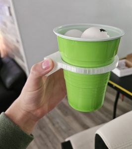
For the XY robot, all of the Amazon-ordered parts have arrived and were fully accounted for, only leaving the 3D printed parts before assembly can begin. Josiah quickly ordered PETG plastic filament (which is recyclable!) and picked it up from the receiving desk on Thursday, and all parts were printed by Friday. Additionally, a custom cup-holding mount was created and also printed, and so everything is now ready to be put together come Monday next week.
One large risk mitigation also raised in this week’s meeting was the problem with loading the YOLO model onto the camera. Fortunately, that has been fixed and the camera can accurately track the ping pong ball. A big priority now is to determine whether the camera being placed where the ball is thrown is adequate to generate accurate depth data to make predictions.
For the KRIA portion, we had a discussion where the interaction between camera and KRIA was looked into. Upon discovering that the camera is able to run CV models, our original usage of the KRIA to do video processing was put into question. Originally we had went with KRIA and then discovered that the camera was so powerful, but by then we had started work with the systems, and found it comforting that although there is a slight overlap in functionality, having the KRIA able to still do video processing is a good backup in case the camera is not good enough. Gordon continued work with setting up the KRIA environment, making steady progress.
We worked through writing our report, which took quite some time to fully flesh out every component. While working through it all and receiving more feedback from the design presentations from last week, we were able to iron out everything we’ve done so far. It was gratifying to see all the progress that we’ve made so far, and very helpful to map out exactly what we need to accomplish next. For me personally, my direction is pretty clear and will elaborate on that next.
While also working on the report, all the components needed to boot up the KRIA were finally here. Now I could finally start the setup process, which first entailed flashing the Ubuntu OS system onto a MicroSD card. I thought that my computer had a port to put in a MicroSD, and it does but for it to actually read on my computer I had to permanently be pressing the MicroSD card into the slot with my thumb. It was challenging to do for the entirety of the duration it took to flash the 10 GB Ubuntu OS onto the card, so I had to use Jimmy’s laptop (which had a wider MicroSD card adapter slot that didn’t require me to manually hold it down to connect) to successfully flash the system on. Once that was done, I could put the MicroSD into the slot, connect the display port to a monitor, connect a USB keyboard and mouse, and plug in the power to start the bootup. The first picture below showcases the bootup sequence when I first plugged it in.
(The picture is too large to include, here is the picture in google drive)
The Ubuntu OS was getting set up automatically, and it was going smoothly. Once it loaded in, I inputted the default username and password (both were “ubuntu”) and was able to login. A picture of the home screen after logging in is included below.
(Again picture too large. Second picture google drive link here)
Now that I could actually login, the next step is to continue to start the setup. Due to the fact that we were mainly working on the design report during the week before fall break, after getting this setup I focused most of the energy there.
For next steps on setup, Varun’s guide on setup should let me continue working. Will be consulting that guide and following along after fall break. Specifically in the guide there should be an example project which I want to try to run. Getting something to run on the board will give me the direction that I need to continue, as right now I am still a little unsure with exactly how everything runs. I know that I will be writing code on my own laptop and transferring files over via ethernet cable, and I know that there also needs to be a second MicroSD card with PetaLinux flashed onto it. Exactly how those all work together is to be figured out as next steps. Although I am a little behind where I wanted to be, I think it’s understandable and more importantly recoverable, given everything else that’s been going on for this class with the proposals and design reports, as well as out of class.
Besides helping write the design review presentation and listening to everyone’s presentation while giving feedback, this week parts that I ordered last week arrived, and I worked through understanding how all of them work together and tried to setup the KRIA on a machine so I could get started. Last week I found a display port to display port connection that would connect to the spare monitor in HH1307, but unfortunately I couldn’t find it again this week. Looked around in the 1300 wing, went to A104 and ECE receiving as well but to no avail. Thus I had to send in another order for that cord, and unfortunately could’t progress with actually setup the KRIA. What I could do was test the cords that did arrive, and I verified that I had everything besides the display.
The display port will put the output of the KRIA onto a monitor so you can see what’s happening, so since I didn’t have that output cord I couldn’t really continue. But what I could do was make sure I fully understood everything else that was interfacing with the KRIA, which there were a few. I consulted Varun for any clarifications I needed and compiled this table below that showcases all the wiring coming in and out of the KRIA.
| Port connections I need | Do I have it? | Port Usage |
| Power Supply to outlet | Yes | Powers Board |
| Ethernet M2M | Yes | Transfer files to run on KRIA, all coding will be done on my laptop and be sent over |
| MicroUSB to USB | Yes | Unknown usage, confirmed by Varun it’s probably unnecessary. |
| Micro SD cards | Arrived | Flash PetaLinux and Ubuntu onto two separate mircoSD cards, so upon plugin the KRIA SOC can read and use the OS |
| USB Mouse | @ home | Interface I/O |
| USB Keyboard | Yes | Interface I/O |
| Display Port M2M | Ordered | To display KRIA output onto monitor |
I’ve identified everything that’s needed, read up more on Varun’s guide as well as the AMD KR260 setup guide, and determined how I will proceed next week once all the components are together. Unfortunately not being able to do much today puts me a little behind on schedule, but that works out a little as this week has been quite busy with other work. Once the parts arrive next week, my workload should also have cooled down a little and I will be able to catch back up. I’m aiming to have the first thing I do to catch up be to connect up the KRIA and run an example project. During this time I can also study up more on Varun’s guide on how to setup the Vitis and Vivado software.