Gordon’s Status Report for 11/30

The 2D ball detection has been completed, and we are now able to reliably detect the ball and generate x and y coordinates for the ball position within the frame of the camera. Jimmy had ironed out the Kalman filter detection code, and so I was able to successfully port that into the 2D detection file. With the Kalman function in, I made it so that when the ball is detected, a recording of the prediction and trajectory gets sent into a video file. We did a quick test, but it turns out that after adding the Kalman function, the FPS dropped down to about 15. This happens because within the code, a new frame is retrieved, then any processing we do on it (detect, then Kalman) will happen and needs to finish before a new frame can be retrieved. This causes the FPS to drop, to the point where the recorded video only spotted the ping pong ball for like 2-3 frames. This led to a pretty terrible Kalman prediction, which is understandable. This is concerning, but we knew that FPS would be an issue from the start. We are still confident that the Kalman prediction is correct, based on Jimmy’s testing with recorded videos. There are also numerous ways in which we can increase the FPS. For one, displaying the frame also takes computation power and slows down the rate of frame retrieval, and since displaying is purely for debugging or demonstration purposes, for actual runs of the system we don’t need to show the frame on a monitor. This reliably increases the FPS by 10+, based on some simple testing I did. Jimmy is also working on using threading to separate the frame retrieval and frame processing, which in theory should also give more frames.

For now the 2D work was done on my end, so I turned my attention to setting up the 3D detection and coordinate generation. This is entering a gray area, as none of us have had any experience working with the depth feature of the camera. I started by piggybacking an existing example that the depthAI library came with. This example worked with activating the left and right mono cameras as an additional stereo camera, to provide depth data of the whole frame. Then there was an ROI (region of interest) in which the depth values within the ROI would be displayed. This ROI is adjustable, and in the example you could move the ROI with the WASD keys. My idea was to activate the color camera at the same time, and use that to detect the ball. Once the ball is detected, move the ROI to where the ball is in order to get the 3D Z coordinate. I wrote out the code, and for the demo we were able to showcase the ball’s depth being reported as we moved it around on screen. There was also an issue with alignment of the two camera systems, but I was able to take some time and fix that. This was promising, but there was still more to do, as the returned depth is not the real world 3D Z coordinate, but the shortest distance from the camera to the ball. This is only speculation, and more rigorous testing needs to be done to determine if that is true. Currently I’ve figured out the math that would translate the shortest distance from camera into the real world 3D Z coordinate, and have been able to generate 3D coordinates of ball position while the camera is on.

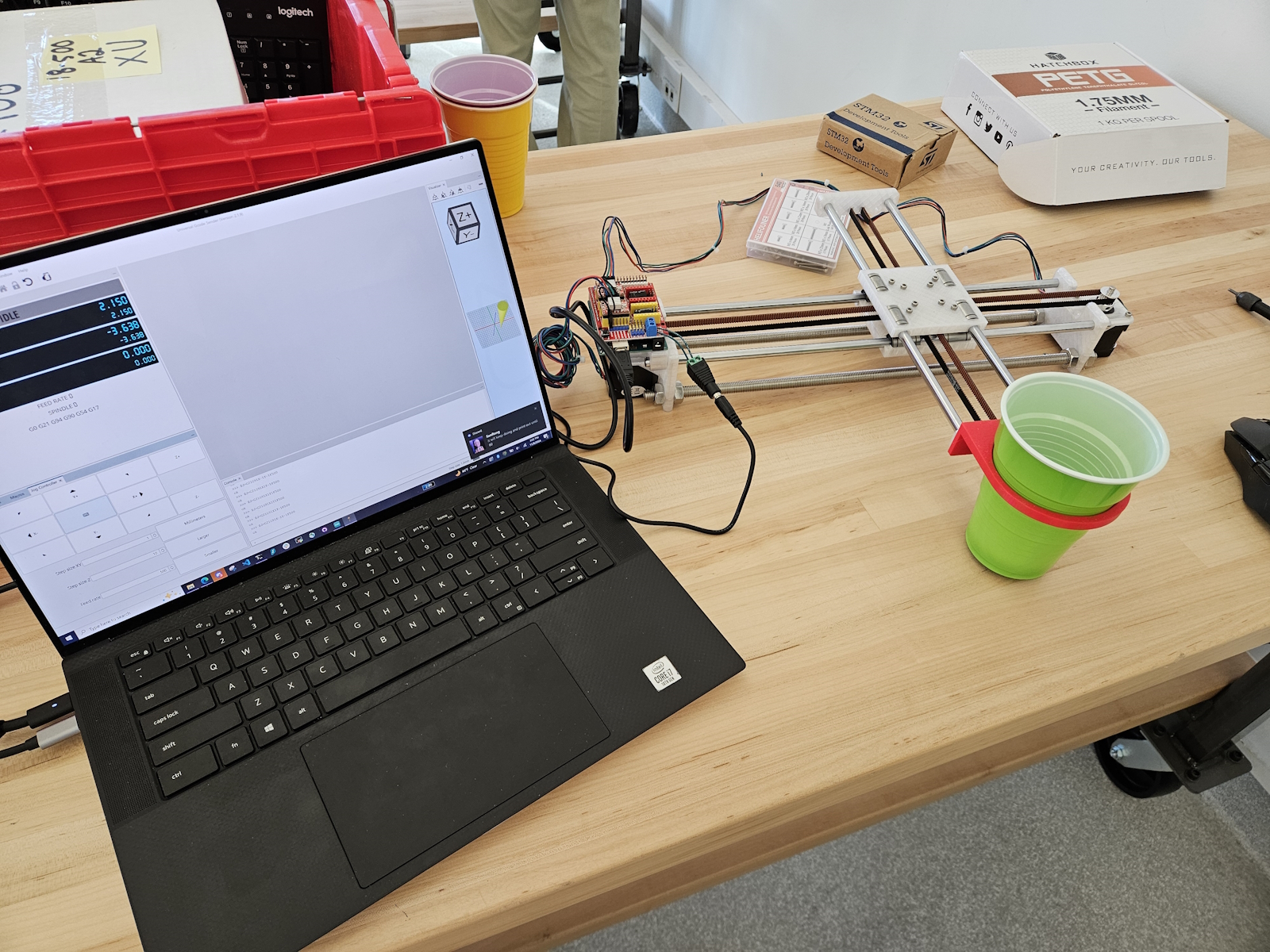
Either way, we are mostly confident about our ability to generate 3D coordinates relative to the camera’s location. The next thing I did was to think through and create a real world coordinate system that the XY robot could also utilize. I wrote out a plan of integrating what we have with the Pi into the robot side, as that still wasn’t super developed yet. Josiah has done a good job with getting G-code to reliably run on the robot, so it is just a matter of accurately determining the landing coordinates and sending them over.

We are coming to the end of the semester, and even though there are still a few big question marks to tackle, we have set up quite a few work sessions to get it all done. I would say that we are currently on pace to finish within the next week or two, but will require a solid group effort to get it done.

As you’ve designed, implemented and debugged your project, what new tools or new knowledge did you find it necessary to learn to be able to accomplish these tasks? What learning strategies did you use to acquire this new knowledge? We recognize that there are quite a few different methods (i.e. learning strategies) for gaining new knowledge — one doesn’t always need to take a class, or read a textbook to learn something new. Informal methods, such as watching an online video or reading a forum post are quite appropriate learning strategies for the acquisition of new knowledge.

I had never worked with either the AMD KRIA or a Raspberry Pi before, so learning the respective tools to get that to work took significant time. I used Vivado and Vitis in the context of setting up the KRIA, and had to look through many AMD/Xilinx guides and forums in small bug encounters. For the Raspberry Pi (RPI), I also had to look through numerous guides and tutorials by RPI for setup and debugging issues (the forum was especially helpful with an issue I ran into with bootup, giving me the exact LED error code and solution). I also used online videos to give me a better sense of what the RPI is and what it is capable of. Then there were the numerous guide pages and forums that Luxonis had in regards to dealing with any code regarding the camera. I also had to rely on TA help from both Varun and Nathan, who had expertise in the KRIA and RPI/OAK-D camera respectively, for other small issues that online resources couldn’t satisfy me for.

Jimmy’s Status Report 11/16

Accomplishments

After experimenting and working with the current kalman filter, I decided to scrap this implementation and work on a new self-implementation of the filter using the numpy library. This yielded really good results, as it allowed me to tune specific parameters that the other model wouldn’t have otherwise. It was able to predict very accurately from visual inspection, although testing will need to be done to make sure that the predictions can be made consistently from different throws and with many variables involved. Also this week Gordon and I together did work on bringing up the OAK-D camera to use on the RPI. There were some issues with the frame rate of the camera, which I aim to resolve using multithreading so that the detection and prediction processing will occur concurrently with pulling in the frames from the camera’s feed.

Schedule

Although I have finished the 2D kalman filter to a very satisfactory level, progress on the 3D kalman filter needs to be done. Things will hopefully be sped up now that Gordon will also be working on onboarding the camera with the RPi so that I can focus all my attention on the algorithmic portion. However, I feel comfortable with the progress that we’re at because the 2D kalman filter can always be used as a fallback incase anything goes wrong with the 3D kalman filter.


Deliverables

Effort will now be made to transition to the 3D kalman filter. I will need to order the white background sheet and stands so that we can accurately replicate the favourable conditions that was used in the original test video so that our camera system will be able to accurately detect and predict the ball. Once the background has come in, I will be able to start recording videos that can be used for the verification stages of the project (see below).


Testing for detection pipeline

  • Setup: 10 different mp4 videos of throws using the same background and similar lighting conditions of the orange ball travelling in a semi-parabola (parabolic trajectory of the throw will range from low to high arcs). 
  • Analyzing: Making sure that percentage of the detections is above 90% (frames ball is detected / total frames). This is because any detection rate below will affect the accuracy of the kalman filter


Testing for the prediction pipeline (kalman filter)

  • Same setup as above, using the detection pipeline output
  • Analyzing: Making sure that the predicted landing position is not fluctuating and is accurate after 25% of the ball’s flight time. This is important because we need to give accurate measurements quickly to give time for the gantry system to move towards. We also need to make sure that the estimated points do not oscillate to prevent wasted movements by the gantry. Accuracy of the landing position is obvious since we want to catch the ball. The leeway given for inaccuracies is proportional to the radius of the cup to catch the ball with

Josiah’s Status Report for 11/16

Accomplishments

This past week, I became more familiar with grbl and G-Codes. I progressively tuned the firmware settings using UGS (Universal G-Code Sender) such that acceleration and feed rate (which is essentially max velocity) were safely maximized without stalling the stepper motors. If the velocity is too fast, the motors won’t be able to handle the strain and just stop rotating. I also created a gcode testfile that translates the cup from the origin to 10cm in the eight cardinal/diagonal directions and back again. This will be used for the demo this next week. Further details on validation are in the team report

Progress

I hope to purchase a different step of limit switches that are more physically compatible with the XY robot. I misunderstood how limit switches function: they have to be physically placed onto the ends of the “gantry” rails such that the levers depress when the cup reaches the end. This sends a signal to the firmware saying “stop moving! you’ve hit the end!” I mistakenly purchased a set of limit switches that are compatible with a 3D printer model, so I’ll get a different bunch to use and wire up. After that, homing should be enabled and we’ll be able to guarantee the location of the cup at all times, even after booting in.

Team Status Report 11/16

For the camera / estimation and tracking pipeline on Jimmy’s end, the decision was made to stop using the OpenCV kalman filter library, and ended up making a good in house implementation which yielded good results. This will be good to set us up as now the 2D visual pipeline is done, which can be a good contingency plan incase our 3D pipeline does not give good results. Some of the risks of this subsystem now lie entirely on the accuracy of the 3D model that is going to be implemented. As for validation, there will be two components to the test for validation for object detection and trajectory estimation. The first is to making sure that the estimates are accurately predicted and tracked. The second is to ensure that the calculation time can be done in a timely manner. The overall goal of the camera and detection/prediction pipeline is to generate a coordinate to send to the gantry so that it can catch the ball in time. Making sure of these conditions are met in the verification of this subsystem will ensure that our overall project goal can be achieved. 

For the Raspberry Pi hardware integration side, a lot of work was put into getting past the setup stage and having functional work be done on the Pi. Jimmy has been working on developing a good Kalman prediction code from a recorded video that he is able to pass into the code. Once I finalized the setup and finished installing the few dependencies, I was able to run the Camera on the Pi. The depth AI package that the camera came with also had many example files that could be run to showcase some of the camera’s capabilities. On Monday I focused on learning how the file system structure is set up and looked through many examples of the camera and what different pieces of code could make the camera do. The next step was to adapt Jimmy’s detection function to take in camera input for video instead of a recorded video. That was successfully done, but the resulting video was only 15 FPS, and it struggled to detect the ball. We had a few ideas of how to improve that, and the details of how we went about implementing that are elaborated more specifically in Gordon’s status report, but essentially we were able to identify that making the camera window smaller greatly increased the FPS, as shown in this table below.

Camera with 2D Ball Detection FPS Experiments

Window Size (All 1080 resolution, cant do worse) Resulting FPS Comments
camRgb.setVideoSize(1920, 1080) 13-15 Default screen size, FPS is way too slow for reliable ball detection. This is without any optimizations of code, which we are looking into
1200, 800 33-35 Ball detection is pretty smooth, need more integration to see if its enough
800, 800 46-50 At this point window size is probably as small as it should go, starts to inhibit ability to capture ball trajectory. Ball detection is super smooth however, a balance between screen size and FPS should be studied
700, 800 ~55 ^
700, 700 60 Achieved 60 FPS, but again window size is likely too small to be of use

The comments provide a baseline overview of what I concluded from this simple verification test. From what I’ve gathered, I believe that this framerate and window manipulation will be a good tactic that we can use to increase the precision and effectiveness of our tracking and trajectory prediction. There are even more tactics that we haven’t tried yet, and plan to test out in these last few weeks if any design requirements have still not been met. There is still a good amount of work to be done to add the third dimension into it, and to convert it to instructions for the XY robot. These last bits of integration we will work on as much as we can as a team, as we still need to figure out how to structure the whole system to give real world coordinates. In general I think our team has done a lot of verification within each of our own subsystems, and it is almost time to start the validation process of integrating all of them together. The RPI and Jimmy’s camera trajectory work are already relatively connected and working, but like aforementioned, connecting to the XY robot will require work from everyone. 

XY Robot:

As described in the design report, there is only a single, though important, test to be run. The big picture is that the robot is agile in motion and precise in positioning, such that it can support the rest of the system. Thus, we have the following validation test:

  1. Supply a series of valid, arbitrary real-world coordinates to the Arduino running grbl firmware through G-Code serial communications. For each coordinate, validate that the robot:
    1. Moves the cup within <0.5cm of the position
    2. Moves the cup to the position within <1.0s

The following conditions should also be met:

  • We define a valid and arbitrary coordinate to be any position within a 10cm XY radius around the origin of the cup.
    • Thus, the cup will only have to move AT MOST 10cm at a time.
  • After each movement, allow the robot to reset to (0, 0).
  • Ideally, configure the firmware to make the robot as fast as possible.
    • We want to give as much leeway to the other systems (computer vision/trajectory prediction) as possible.

For the demo, I’ve made fairly good progress towards most of these goals. The firmware is set up to a possible maximum configuration of XY acceleration/feed rate, though I think this can be further configured. The demo entails moving the cup 10cm in the 8 cardinal directions + diagonals, and back to (0,0). This leads me to believe that the robot should be able to handle any instructions that call for less than 10cm of translation too. While unrigorous, I’ve also timed these translations, and they seem to fall within 0.3-0.4s, which is fairly decent.


Future testing would be to set up a python script that communicates G-Codes directly to the arduino through the serial port. I believe this should be possible. This can automate random valid coordinates as well. I also need to purchase a different set of limit switches. I had a misunderstanding over how they function, and so in order to enable homing, must set up four at the ends of each rail.

Gordon’s Status Report for 11/16

A lot of progress was made regarding getting things working on the Pi + camera setup. A few extra dependencies were set up on the Pi, and I was able to run all the example files that the depth AI library of the camera came with. There was actually an issue with connecting to the camera to run certain examples, because we ran into current overcharge errors. Did some research, and found out that the Oak Camera actually came with a Y adapter, which allows the input to the camera to be split into 2, allowing the camera to receive input from the Pi as well as get powered from an external supply. This meant the RPI’s limit of 1.2 output Amps could get bypassed by powering the camera separately. 

I took some time to understand how the code behind the camera works, looking into the cv2 library and the depth AI library, both areas that I had previously never worked with before. This was also done under Jimmy’s guidance, as he explained how his code was setup and the pipeline that he was following. Currently we have a black box model in which Jimmy is developing the trajectory prediction with the Kalman filter off of a prerecorded video, assuming that the camera will be able to connect. Thus I took some time to understand how Jimmy was running his code, and adapted it to allow for the Camera input to be used instead of the prerecorded video. I also added in a feature to allow us to see what the FPS of any given video was.

It was successful in that we were able to run the ball tracking with input from the camera, but we realized that the resulting FPS was a measly 15, too low to reliably track the ball. Our initial thought on how to tackle this was to actually attempt making our program multi threaded, having one thread be handling the camera sending in frames, while the other thread worked on processing those frames. We thought that this would help since in the main code, each frame had to come in and get processed before another frame could come in. All the time it took to process each frame (i.e. do the ball identification) was thus causing the FPS to drop. We ran that code but then the Pi softlocked, and we were stuck. The Pi would get stuck on the boot up screen, and was major cause for concern. I ended up having to re flash a new SD card with a blank OS, and restart the setup process with all the dependency installation. Thankfully the second time around was much easier as I knew what to do, and also we had our code backed up and could get back to where we were relatively easily. 

I also setup remote VNC forwarding, which allows me to essentially have the Pi running on my computer, eliminating a need for a monitor. However it is slightly laggy on the computer, so a monitor is still preferred. Once returning to the point where we had the program capable of tracking the ball at 15 FPS, I dug around the code and given example files to try and see if there were other ways to improve the FPS. One thing I found that made a big impact on FPS was the window size of the camera. Currently it was defaulted at a 1920×1080 wide window, which is actually bigger than we need it to be. Decreasing the window size significantly improved the FPS, with data and some comments shown in this table below.

Camera with 2D Ball Detection FPS Experiments

Window Size (All 1080 resolution, cant do worse) Resulting FPS Comments
camRgb.setVideoSize(1920, 1080) 13-15 Default screen size, FPS is way too slow for reliable ball detection. This is without any optimizations of code, which we are looking into
1200, 800 33-35 Ball detection is pretty smooth, need more integration work to see if 35 FPS and this window size is enough
800, 800 46-50 At this point window size is probably as small as it should go, as it starts to inhibit ability to capture ball trajectory. Ball detection is super smooth however, a balance between screen size and FPS should be studied
700, 800 ~55 Same as 800, 800
700, 700 60 Achieved 60 FPS, but again window size is likely too small to be of use


This gives us a lot of confidence that the tracking would work in a 2D sense. There are still quite a few more next steps, as I haven’t added the Kalman filter portion into the video, and we are also missing the third dimension. Another unknown is the connect between RPI and instructions for the XY robot, as we haven’t looked into how the whole systems are going to physically connect, and how we can construct a coordinate system that all subparts will recognize. The next few weeks will be crucial in project integration, but I’m confident that we are on track to be able to successfully integrate everything. 

Team Status Report 11/09

Status Report for 11/9

For the camera pipeline on Jimmy’s end, a lot of progress was made this week getting a proof of concept implementation of the kalman filter, where it is able to project out estimations of where the ball is flying towards (demo can be seen on individual report). However, a few issues did come up in the process regarding accuracy, some oscillation behaviour with the estimations, and the fact that this also needs to be implemented with both X, Y, Z coordinates, rather than X, Z which is the implementation right now. However overall, this is a really good physical evidence that a kalman filter would really work and give us the best estimate as opposed to the sole physics model. One pivot that was made was scrapping the YOLO model as it was too resource intensive and would lower the FPS of the camera video output, opting for a filter / colour tracking approach (more discussed in individual report). There are some drawbacks to this approach, as we will need to fine tune the colour HSV ranges to detect depending on the lighting conditions, and the camera colour range. Additionally, since we have pivoted to the raspberry pi, some work will be done in the following week between Jimmy and Gordon to make sure that the bringup of the raspberry pi goes as smoothly as possible, making sure the loading of the camera pipeline and the object detection and kalman filter is functional on the RPi. 

After consulting with Tamal and Nathan and receiving their approval with switching from KRIA to Raspberry Pi (RPI), we were able to place an order for an RPI5 and officially move into doing it all on the RPI. We repartitioned our roles, as without the KRIA Gordon has less work to do in terms of hardware integration. Gordon will still be handling the connection between OAK-D to RPI and RPI to robot, but now has a little more liberty to help out with Jimmy or Josiah on other tasks. 

For Gordon’s RPI setup and other hardware integration, we were able to receive the RPI and could start the setup immediately. My personal status report goes into a lot more detail, but essentially we were able to successfully setup the RPI after getting through a few unexpected bumps, and are now able to SSH into the Pi directly from anyone’s laptop. Here are the steps to SSH:

  1. Connect Pi to CMU-DEVICE
  2. Connect laptop to CMU-SECURE
  3. In terminal on laptop, type username + passwd

With the help of Jimmy, using Conda we were also able to setup the Depth AI library and other dependencies needed to run the code on the Pi. For next steps, Gordon will do some research into how the code runs and look into how we can transfer data from the camera output into the robot system. Specifically, find a way to get rid of the Arduino that Josiah is currently using to test the robot, as if we can get rid of that middleman then we save on latency.

On Josiah’s end, the construction of the robot is practically complete. Controlling the stepper motors is possible with GRBL firmware loaded on the arduino, and a Universal G-Code Sender hosted on a laptop. It’s promising seeing it all put together at last, despite some frustrating circuit-level debugging. It turns out that the motor drivers–mounted on the CNC shield–are highly sensitive to electrical interference, and just a light touch can grind proper motor rotation to a halt. Additionally, a second cup mount was designed and printed to accommodate for a belt bearing that stuck out and made the previous cup mount incompatible with the system. Future work is further familiarizing with G-Codes and figuring out “inverse kinematics.” I place this term in quotes, because the task is far simpler compared to more sophisticated robotics applications.

Jimmy’s Status Report 11/09

Accomplishments

A lot of progress was made on the kalman filter, including a prototype of an accurate model that is able to track the ball in flight and estimate it’s landing position through visual input. At first, this was done on the YOLO + background subtraction MOG (gaussian) pipeline, however upon integrating this with the OAK-D camera, I realized that this would cap the frames per second (FPS) rate of the camera video output to only 15 FPS, which is much lower than what we need to generate an accurate estimate with the kalman filter. In order to combat this, I decided to pivot to a new object detection model, which is using a colour detection model that detects a specific range of HSV values, also with contour detection for the curves of the ball. This yielded good results for the tracking, which will also help the camera yield a higher framerate as it will not be competing for resources on the camera side. Regarding the kalman filter, I have refined the filter even further to produce good results shown in the video. Although I needed to work on a 3D approach, I spent the time refining the model with the 2D approach before feeling confident enough to work on the kalman filter with 3 dimensions. At the end of the week I also helped Gordon with the initial bring up of setting up the raspberry pi and getting the initial python camera libraries set up on the board.

Schedule and Deliverables

I have made a lot of advances on getting the kalman filter working, so I am on schedule currently. Work needs to be done migrating from a 2D approach to detecting and tracking the ball movement to a 3D approach, so this will be a top priority for next week. At the same time, I will need to find techniques to refine the estimation accuracies of the kalman filter on the 2D version, as it is giving some inaccurate results. I have also observed an oscillation in the predictions that the kalman filter is giving, so I will either have to debug this issue or find a mitigation through a smoothing function or integrating PID control when passing the coordinates onto the gantry system. As Gordon is also working on the bring up of the raspberry pi, some work will be done next week integrating the camera pipelines, installing dependencies, and making sure that the pipeline can run on the board.

Josiah’s Status Report for 11/9

Accomplishments

The robot moves! With the timing belt and pulleys in place, I mounted the Arduino, CNC shield, and motor drivers to control the steppers. After some difficulties while testing the stepper motors, I eventually came to several conclusions. The first is that the motor drivers (which plug into the CNC shield, which itself is plugged into the Arduino) are HIGHLY sensitive to electrical interference. Even lightly touching a driver can result in stalled motor motion. Later, online resources suggested to unplug the 12V 2A power supply before changing any connections with hot wires. I was very confused and at times exasperated when the motors would grind to a halt seemingly arbitrarily, and I suspect this issue to be a result of the two factors at the same time. I got GRBL (a free, open-source firmware that controls the motion of CNC machines, short for “G-Code Reference Block Library) uploaded to the arduino, and can send G-Codes through an external Universal G-Code Sender that controls the stepper motors in tandem. While I didn’t get a ton of time to play with it, it appears to be very powerful.

On another note, I had to do a small modification to the cup mount to accommodate for a belt bearing. The bearings slightly stuck out, and so I made a small cutout of the existing part. As bonus, I totally nailed the design of the cup mount. The cup is held just slightly above the surface of the table!

Progress

I expect to familiarize myself better with the XY robot controls, and see if I can send a single command to make it move to a specific location XY location. I did see a “set origin” button in the G-Code sender, so I believe this will be possible. In the future, I will also want to procure a soft material to line the cup mount, as the stepper motors can vibrate the entire system quite loudly. This will dampen the cup vibrating on the mount, which can be very loud.


Gordon’s Status Report for 11/9

After making the monumental decision to shift away from the KRIA and into the Raspberry Pi last week, on Monday we confirmed our ideas and plan with Tamal and Nathan, and could now proceed with figuring out the details on what to do next. After getting approval, I ordered the Raspberry Pi 5 from the ECE 500 inventory, and started to do more research into its capabilities and if it would suit exactly what we needed. We also found that it could connect to the OAK-D camera with ease, as Nathan had used it in his project. We also found a guide made by Luxonis on how to connect a raspberry pi to the OAK-D, so I spent some time reading through it. The Luxonis guide had links to a few Raspberry Pi OS files that had the DepthAI and other dependencies pre-installed, so I spent some time trying to flash those into the spare SD cards we have. My laptop has a slot for the microSD cards, but previously I had been misusing it, as I thought I had to hold in the card with my finger to have it be read. That was not the case, I simply had to use my nail to press the card further into the computer and it would lock and hold in place. Knowing that earlier would have saved my finger a lot of pain but at least I was able to figure it out eventually. Using the Luxonis OS installer was actually not the standard Raspberry Pi Imager, and there were some issues with the one that they provided. I ended up installing the Raspberry Pi imager as well, and had multiple copies of raspberry Pi OS on a few SD cards.

On Wednesday, the Pi arrived, and luckily the kit that it came in had all the port connection wires that I needed to plug into a monitor. I tried connecting it up and seeing what would happen, but plugging it in and sliding in the microSD card only gave me a black screen. This was concerning, as I wasn’t sure if the OS I grabbed from the Luxonis guide was good or not, and I also didn’t know if it was an issue with the monitor or the Pi itself. I ended up having to try all combinations of my installed OS files and a few different monitors in the 1300 wing, to which nothing worked. I realized that the Pi was displaying an error code through the LED, and through that was able to find out that there was actually a SPI EEPROM error. This meant a corrupted image with the Pi, which was something I had no control over during the setup. I ended up solving the issue by following a guide on the Raspberry Pi forum, and the Pi was able to display on a monitor. Here’s a link to a picture of it successfully displaying: (Too big for upload on here)

I was now able to test the different OS files, and found out that the Luxonis provided ones were either corrupted while flashing or not compatible with the RPI5. Thus I had to stick with the default Raspberry Pi OS, and started looking into how to install the required dependencies and libraries. 


At the same time, I started to setup the SSH from our computers that we would need to access into the RPI to run our files. This required getting on the same network from my computer and the RPI while the RPI was connected to a monitor. I had to request a new device to be added to the CMU-DEVICE wifi, as when my computer is on CMU-SECURE and the pi is on CMU-DEVICE, we are technically on the same network and SSH is possible.

After we managed to connect via SSH, we are able to unplug the RPI from the monitor and just connect power to the RPI and SSH into it, which makes operating and doing work on it much easier. While SSH’ed, I was able to then setup the DepthAI library and other dependencies that our code would need to run. This was done with the help of Jimmy, who showed me how to setup the Conda environment to do this.

We made pretty good progress with setting up the RPI and all of that, so next steps would include figuring out how the current camera code works, because we now need to interface with getting camera data into the robot. If we can get rid of the middleman Arduino that currently Josiah is using to test the robot, we should be able to save on latency. 

Jimmy’s Status Report 11/02

Accomplishments

This week, I worked more on the camera integration, working to produce an output that would be suitable for the kalman filter to run on. I integrated the depth sensor with the object detection model, so now it is able to generate a X, Y, Z coordinate position of the ball as it is being detected and tracked in real time. I also worked on improving the accuracy of the kalman filter, looking at multiple different implementations using OpenCV, and also read some papers to conceptually understand the background knowledge in the case that I would need to write my own filter. Finally, to help with the camera vision pipeline, I also added a background subtraction filter to allow more ease for the yolo model to track fast moving objects. This gave good results, as now putting video playback onto the detection model, it was able to detect the ball in every single frame of the video. 

Schedule and deliverables

With a lot of work being done in the camera pipeline, I am feeling good about being on schedule overall. However, the kalman filter still remains my biggest concern, as it is difficult to get a working implementation without any good documentation or background. My main goal next week is to get the new implementation of the kalman filter working and test out a proof of concept. It will be my top priority as the results from this POC will determine whether we would need update our design for the camera location and camera angle.