Here is our Video!
Check out Final Project Documents for the poster, final presentation, and report.
It’s been a super fun semester and thanks to anyone following along : )
Carnegie Mellon ECE Capstone, Fall 2024 — Josiah Miggiani, Gordon Xu, Jimmy Zhou
Here is our Video!
Check out Final Project Documents for the poster, final presentation, and report.
It’s been a super fun semester and thanks to anyone following along : )
This week (and the last week) was all hands on deck with integration. We focused a lot on actually mapping out the system, and setting up the coordinate grid. The translation between camera into real world distance was made, and we also moved our system into the 1200 wing for testing. Our backdrop arrived, and we were able to set it up in the back of 1207. Since we are having a system where we need to capture the full arc of the throw, we found the optimal camera configuration that includes the robot, backdrop, and the full arc of the throw.
Once setup was complete, the three of us all worked on setting up the complete pipeline for the 2D version. The third dimension is coming from depth in the camera, which we had to put on hold. More information about that in Gordon’s individual status report. We had created a file in which all the components (camera with detection and kalman interfacing, connecting to the Pi, translation into G-code for the arduino) were able to run, but with testing found out that the Raspberry Pi was not powerful enough to handle all of it at once. More information in Gordon’s individual status report. We ended up just using Jimmy’s laptop to run it, and it was able to perform very nicely. We actually were able to get the full pipeline working, and have multiple recordings of us throwing and the system catching the ball.
For next steps, we are working to integrate a second camera to provide the missing dimension. The decision of giving up on the depth capability of the depth camera and getting a second camera setup was made only after meticulously attempting to debug and make workarounds on how the depth camera could not handle everything running. Even using the laptop instead of the pi, there simply was not enough processing power to get enough frames to reliably capture the ball’s depth coordinate. Specifically, the ball’s location could be tracked, and we moved the Region of Interest to those coordinates and requested the depth of the ROI. But in the short time it took to actually get that request fulfilled, the ball had already moved out of the region. We tried all sorts of methods to move around the ROI or make it bigger, but everything led to a buggy implementation where the depth coordinate simply could not be reliably generated. We also tried getting rid of the ROI in entirety and just look into if they can return depth coordinates at a specific point, but even that was unsuccessful. We were able to get the ball coordinate when it was moving at slower speeds, but in order for it to matter it needed to capture depth coordinates of an in-flight ball, which it couldn’t do.
We have tested with a second camera positioned facing the throw, and have good reason to believe that we can modify our code from the first camera to successfully integrate the second camera. This is because the only force acting on the x and z axis of our throw is air resistance, so the detection and Kalman models we already have for the x axis should be able to easily convert to the z axis. Jimmy successfully wrote up the code, and with some preliminary testing we found it to work pretty well (more details in Jimmy’s individual report). We are right here at the end, as once the second camera gets integrated, we will have the missing dimension and we will be done.
List all unit tests and overall system test carried out for experimentation of the system. List any findings and design changes made from your analysis of test results and other data obtained from the experimentation.
For the camera, we did testing on if detection and Kalman filters would work for a 2D plane first, off a recorded video. Then we moved into testing how well those same functions would run with live camera feed video. After we got 2D working, we ran the same tests on 3D to see if the FPS and functionality is still adequate. From 2D testing, the Pi showed promise and was able to detect pretty well. But once we switched to 3D, testing results were not good enough with the Pi. This led us to abandon the Pi for a laptop, as explained above and also in Gordon’s personal status report. For further 3D testing, we determined that the single depth camera was also not adequate to our standards, and made the design change to use 2 cameras. That was explained in this status report as well.
For the robot, we tested the movement of the robot. We tested moving in our full coordinate range, and verified that it can move the whole range. We also ran some tests on the timing of how quick it could move from one end to another. Then we did tests on if the robot could receive multiple movement commands in rapid succession. The robot was able to pass all these tests to our standards.
Accomplishments
Over this week, I was able to fully integrate the camera detection pipeline, tracking and kalman filter implementation to make a series of predictions and finally link that to the gantry system. The final result was a system that is able to predict throws from the user on a single axis. I then tried to debug the issue of the 3D depth detection on the Luxonis camera with Gordon, where we eventually deduced that the depth was a no-go for reasons outlined in the team report. We eventually switched gears to using a second camera, which I have prototyped up some code that successfully predicts the horizontal direction of where the ball will land, from a front-facing camera placed behind the gantry system, getting a full-view of the user throwing the ball so that we can use this prediction in-place of the original depth measurement. This uses the same kalman prediction pipeline as the side-view camera and an adjusted detection filter (an addition of MOG background subtraction and also using moments capture rather than contour extraction). Here are the results:
Schedule
Since we have pivoted to a much easier concept by using a second camera, we are back on schedule and implementation details are fully complete – we are waiting for the second tripod to arrive so that we can test the full system. What remains is the balance between the poster/video/final report submissions with the final integration sprint that needs to be completed in time for the final demo.
Deliverables
Testing of the final integrated product will need to be completed once the second tripod has arrived. I will also finish up the code that integrates the side-view camera detection/prediction and the front-view camera detection/prediction whilst waiting for the tripod. I will also finish up some logic that will only allow for the front-view kalman pipeline to be running when the side-view camera has detected the ball in it’s frame, as to prevent the front-view camera erroneously to begin predicting before the user has even thrown the ball.
The final report… at this point, we’re laser focused on integrated everything. Besides the robot and finalizing the demonstration setup (the wood base-board warped due to being so thin… tape everywhere!), I whipped up a metrics visualization script that plots shots made onto a graph. It differentiates between shots outside of the robot’s catching area, shots made inside the square area, and shots made in the cup without needing assistance (a splash!). This was accomplished through matplotlib. I need to add a bit more to show accuracy, shots made percentage over a total session, and I think it would be cool to include a color map based on how far the shot is away from (0,0). But it’s mostly complete.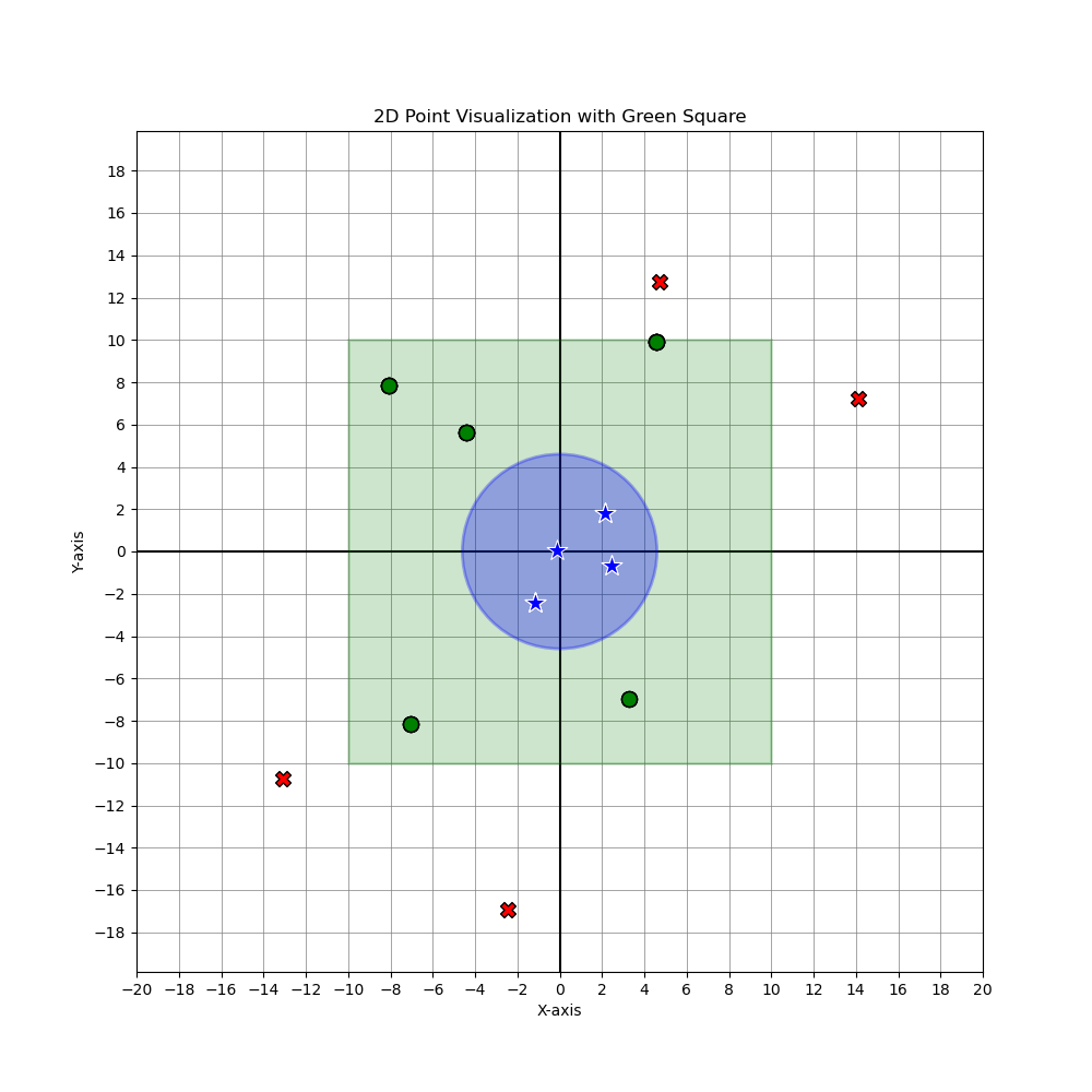
Progress
I’ve additionally been helping Jimmy with integrating the robot with the camera + Kalman operation. Next is shifting gears to churning out the poster and video.
A lot of effort this week was put into making calibration work for the 2D pipeline. We decided to work on just 2D for now because of an issue with depth sensing. The team status report touches on the success of the 2D pipeline, so here is more on what happened with the depth sensing.
The depth sensing code that I was working on was successful…but only if the ball was moving at a slow to moderate speed. The way that it works is that the RGB camera is turned on and used for detection of the ball. Then the detected coordinates are used to move the region of interest (ROI) to the right spot, which will allow for the spatial camera to give us the depth of the ball. The spatial camera is only able to return depth coordinates within the ROI, and so we always had to move the ROI to get our desired depth. The issue was, due to limitations of the camera and RPI processing speed, once the ROI moves into the detected ball coordinates, by the time the spatial camera returns the depth at the ROI, the ball has already moved out of the ROI. This is why it would work for slower speeds of moving the ball around, but it isn’t quick enough to sense the ball as it is being thrown. The 2D ball detection still works at the speed of throwing the ball, but the depth ROI is unable to keep up.
I spent a lot of effort looking into what could be done. The limited Luxonis and depthAI documentation online was hyperfocused on the provided example code didn’t prove to be of much use, and I had to resort to a lot of trial and error with which lines of code caused it to run too slowly and what could be done to improve it. Even switching out the RPI for a laptop proved to be too slow. We simply required too much computation to have both the RGB and spatial camera systems running at the same time, but there was not a way to get the pinpoint data that we required elsewise. I also tried to make a static ROI in the middle of where a throwing arc would be, and sense the ball as it passed through the ROI on screen. This was an attempt to take advantage of how the change in depth should be mostly linear, hoping that getting at least one coordinate would help with predicting the final z coordinate. Given how much effort and time was being put into making it work to no avail, we pivoted into looking into getting a second camera as another option for success. Given the limited knowledge we had, we decided to switch to a different method to get a different shot at creating the final product that we wanted.
I placed orders for setting up the 2nd camera, and did some preliminary testing on if it would work. Since our 2d model was working so well, we are confident that it will work for a front facing camera to get the z axis. For the next week, we will make sure that it gets smoothly integrated, and also put effort into the poster, video, and final report.
Accomplishments
Over the past two weeks, I was able to complete the 3D implementation of the kalman filter – this is good news as this means all the coding on my ball detection, tracking and prediction has been completed! I have also completed the integration of the camera pipeline onto the raspberry pi, which means that it is able to feed coordinates to the x-y gantry system. Some obstacles that I ran into when integrating the pipeline included the frame rate problem – when taking camera frames in the main while loop, the detection and kalman code would take a non-trivial amount of time. This would cause the framerate of the overall pipeline to drop to about 15 FPS, which is not enough for our needs. The solution we discussed was to implement multithreading – one thread to take in camera frames and run the detection filter, and pushing the detected ball in x-y coordinate form into a synchronized queue data structure. The second thread would pop coordinates out of the queue, and run the kalman filter to output the predicted coordinates, which would be fed into the serializer module for the arduino. This solution deemed to be extremely successful, allowing the framerate to increase to 60FPS, which exceeded our expectations.
Schedule
Currently, we are a bit behind schedule as we still need to fully test and verify our system is correct. However, we are opting to use the slack time that we allocated ourselves for this task, and so we are confident that we will be able to complete all these tasks within the final demo day.
Deliverables
I need to finish testing of the 3D kalman filter with the real-time data once Gordon has fully tuned the depth information from the camera and also once the white backdrop has arrived (so that we can fully detect the ball in all lighting conditions). I will also need to tune the parameter of the kalman filter, so the gravity parameter in real time calculations is different to the gravity parameter used in the initial testing videos. I will also help Josiah and Gordon to make sure that whatever needs to be done is completed before our final demo.
Status Report for 11/30
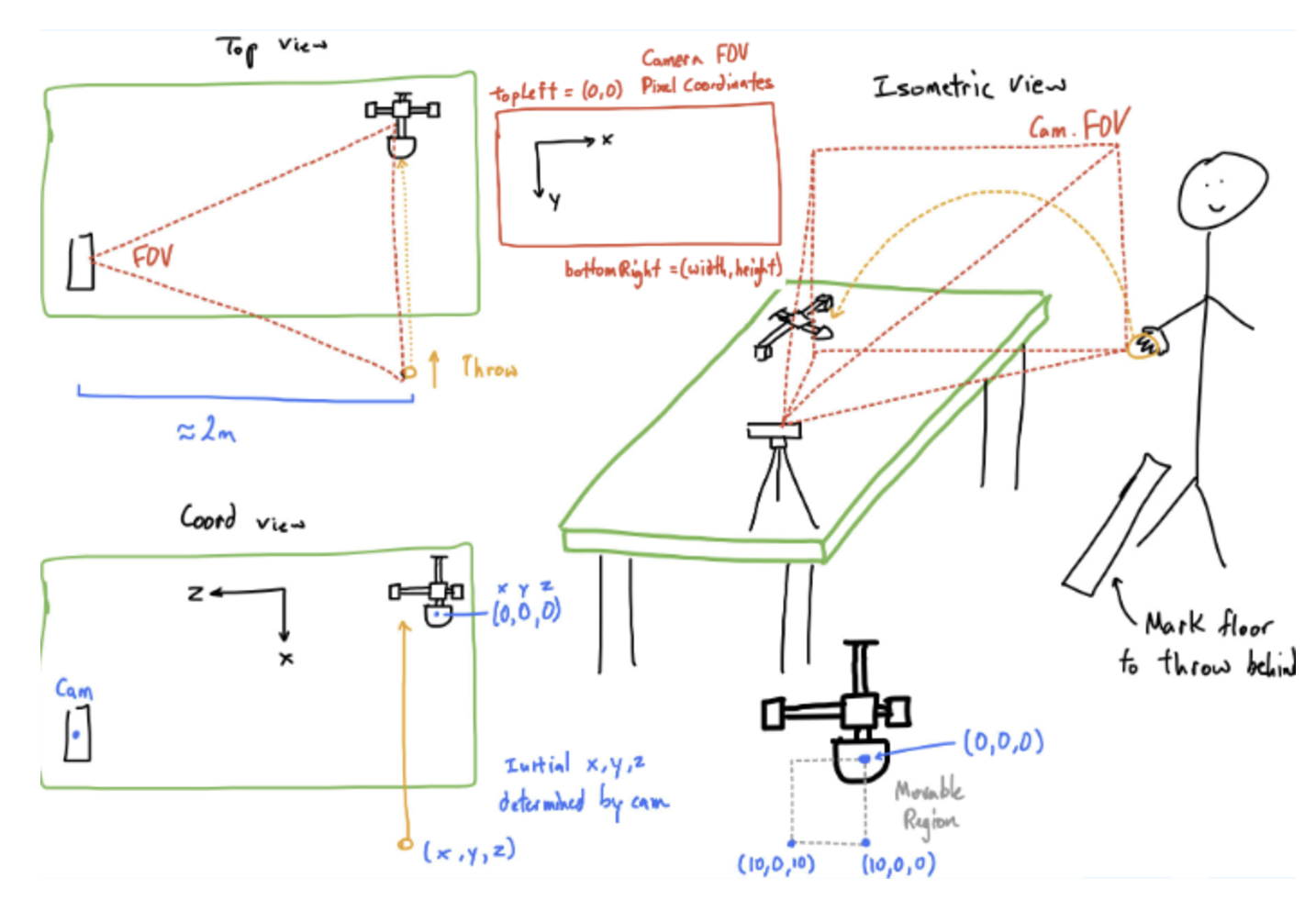
As each of our individual portions began to conclude, we started to focus on the integration of the project. Check Gordon’s individual status report for more details on 3D coordinate generation. Since Gordon is in charge of most of the hardware integration section, I took charge in drawing out what the real world mapping would look like, and did a calibration test to see how many pixels on the camera frame was equivalent to how many centimeters in real life. Below is a picture of how our mapping is visualized and connected between the Camera/RPI and the XY robot.
For the code that would integrate it all, I worked with Jimmy to create “main” function files that would tie together code to operate the 2D and 3D cameras, detection, kalman filter, and G-code interface. This is our final pipeline, and we were able to get it to a point where all we needed was to physically align and calibrate the camera in real life, and could begin our testing of the project from camera to robot. We actually made 2 “main” files, one for a simpler 2D pipeline (this would not have the depth camera activated) and one for the whole 3D one, since I was still fine tuning the 3D detection and coordinate generation while Jimmy created the 2D pipeline code. We are planning to first test the 2D pipeline, as switching to 3D will be as easy as running a different file.
On the camera and prediction side for Jimmy, all implementation details have been completed. The 3D kalman filter was completed, however testing needs to be done to verify the correctness using real world coordinate systems, for tuning for acceleration variables. Some roadblocks that was run into included the producer/consumer problem between threads when using multithreading to increase the camera FPS, which was eventually resolved. Currently, the biggest unknown and risk for our project remains to be the integration, which we will be working tirelessly for until demo day. Jimmy will be focusing mostly on the software integration of the camera detection, tracking, prediction on the raspberry pi. The following video is a real-time capture of the detection, and kalman prediction being done in real-time for a ball being thrown (more details in individual report)
On the robotics side, everything is complete. See Josiah’s status report for detailed documentation on what was accomplished. The big points are that serial communication through a python script is functional with the firmware running on the Ardunio (use a simple USB cable), and it’s possible to queue multiple translation commands to grbl because it has an RX buffer. Therefore, it integrates well with the Kalman Filter’s operation, as it generates incrementally better predictions iteratively. These can be passed to the robot as updates are made.
Accomplishments
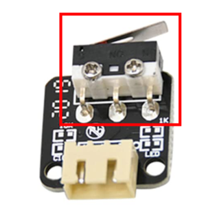
In short, the robot really is complete! It was mainly finishing touches. Instead of purchasing new limit switches, I just snipped the actual switch from the end stop that was intended for a 3d printer. From there, a little bit of soldering, wiring and glueing completed my homing setup. From now on, the origin will always be well defined and replicable, and therefore all translations well defined and replicable. I only used two limit switches, so hard limits aren’t quite enforced on the +X and +Z axis… but ideally we never exceed 10cm in any direction with software-enforced checks.
I’ve successfully migrated away from UGS and have implemented serial communication with the Arduino running the firmware through a python script. This will integrate cleanly with the rest of the system (RBP, camera). All integration requires on the side of the Pi is to first establish a connection over serial (USB) with the grbl firmware, and initialize some processes and configs, namely homing, feed rate, among others. Then whenever a prediction is made, simply call gcode_goto(x, y) to move the cup.
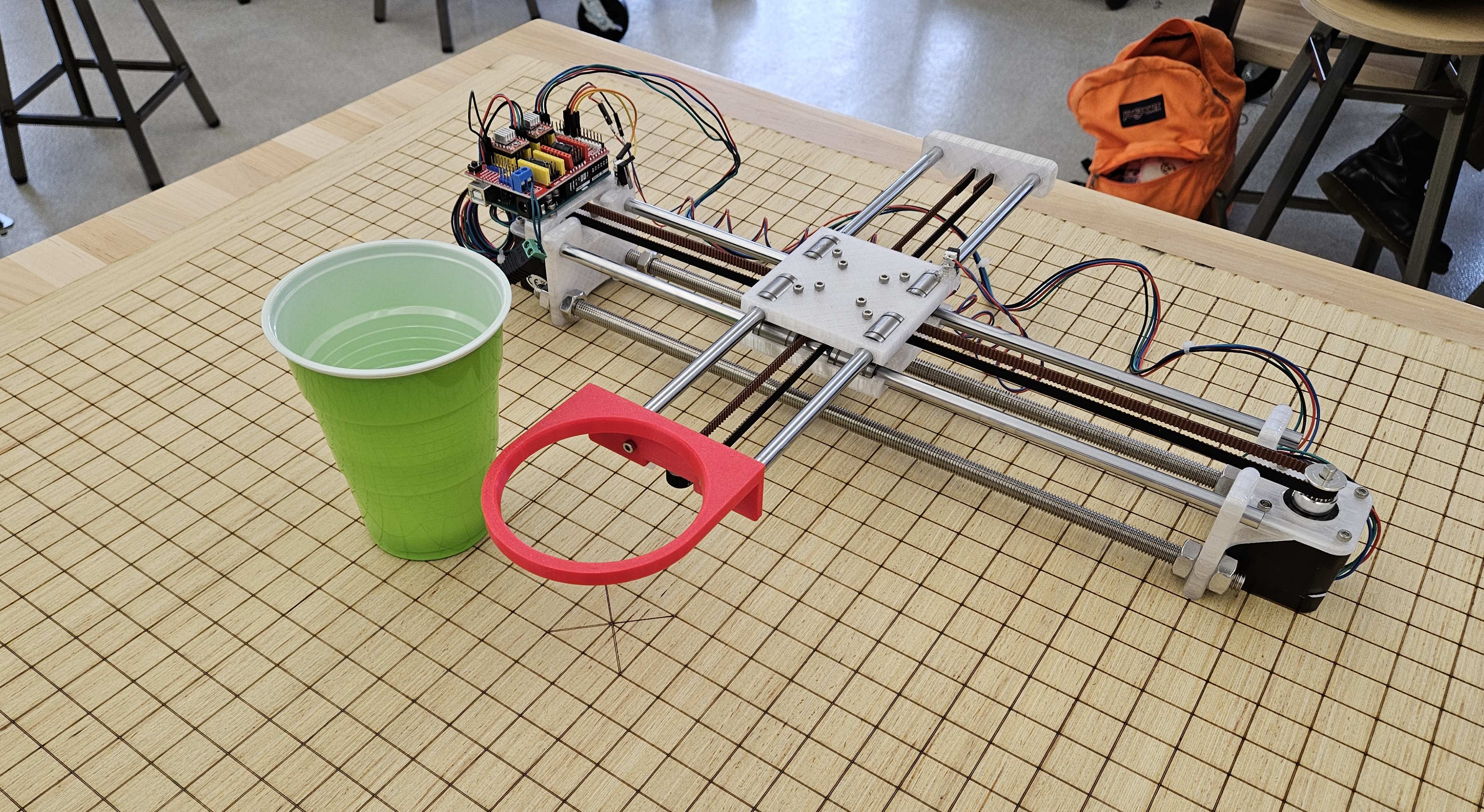
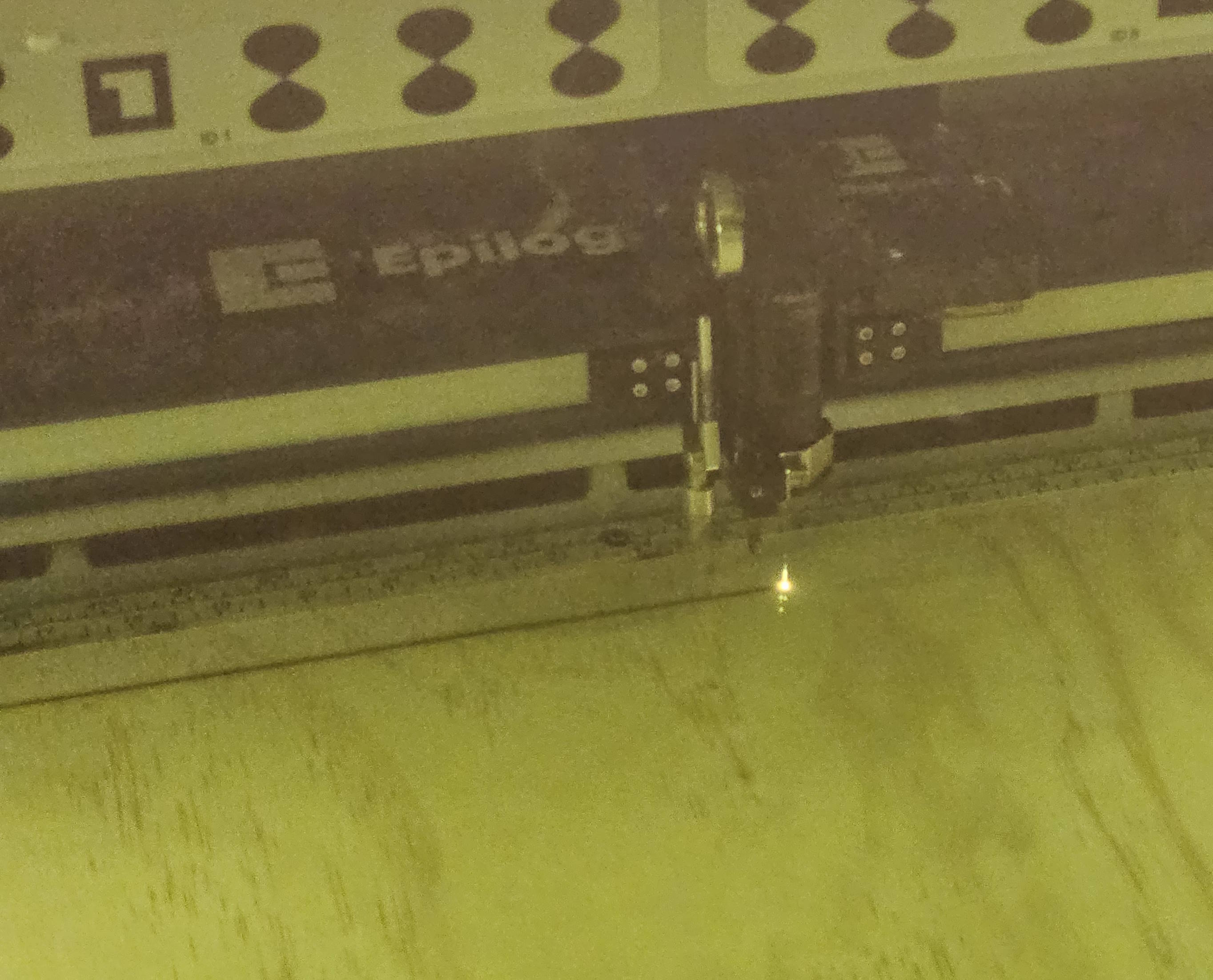
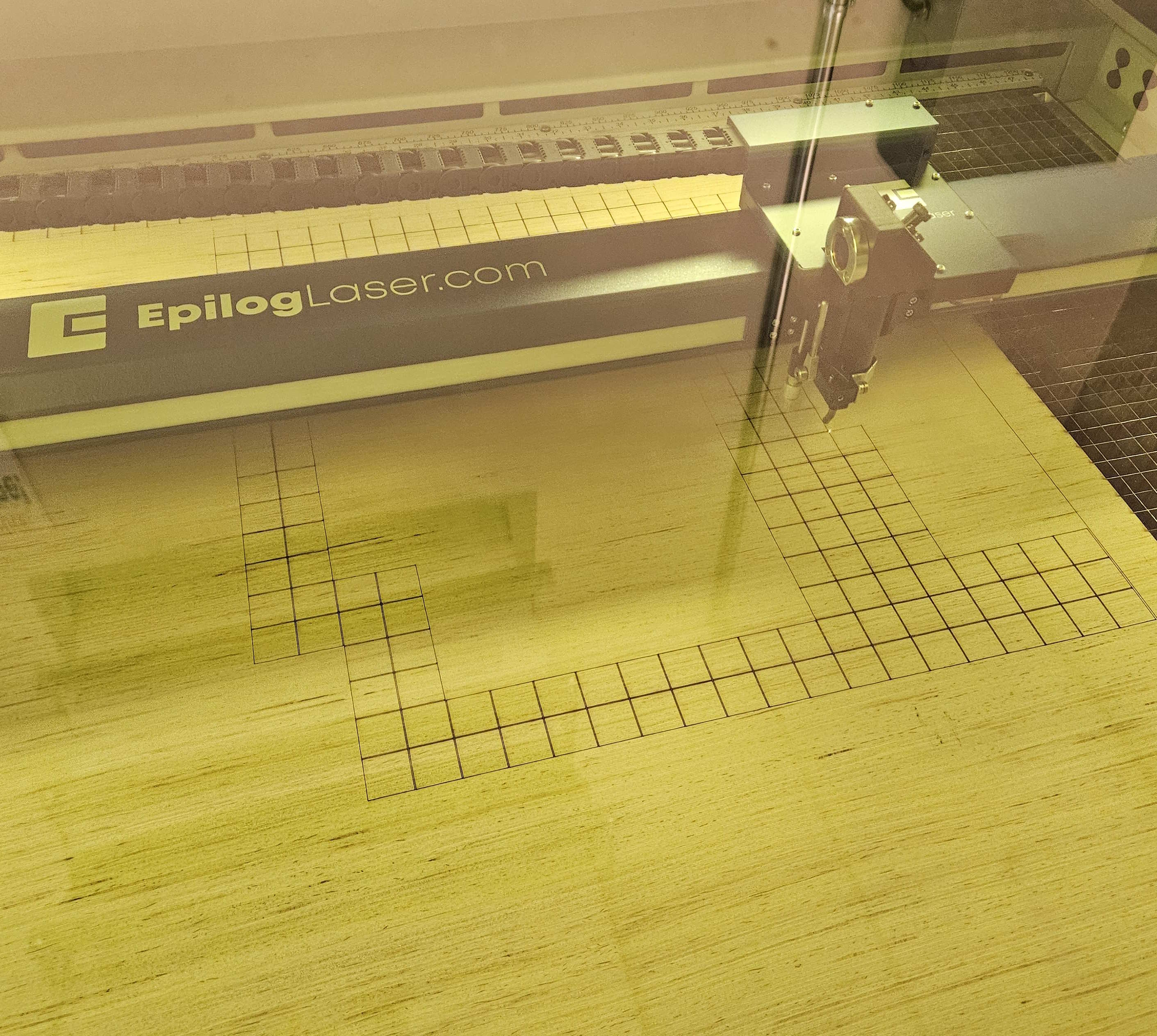
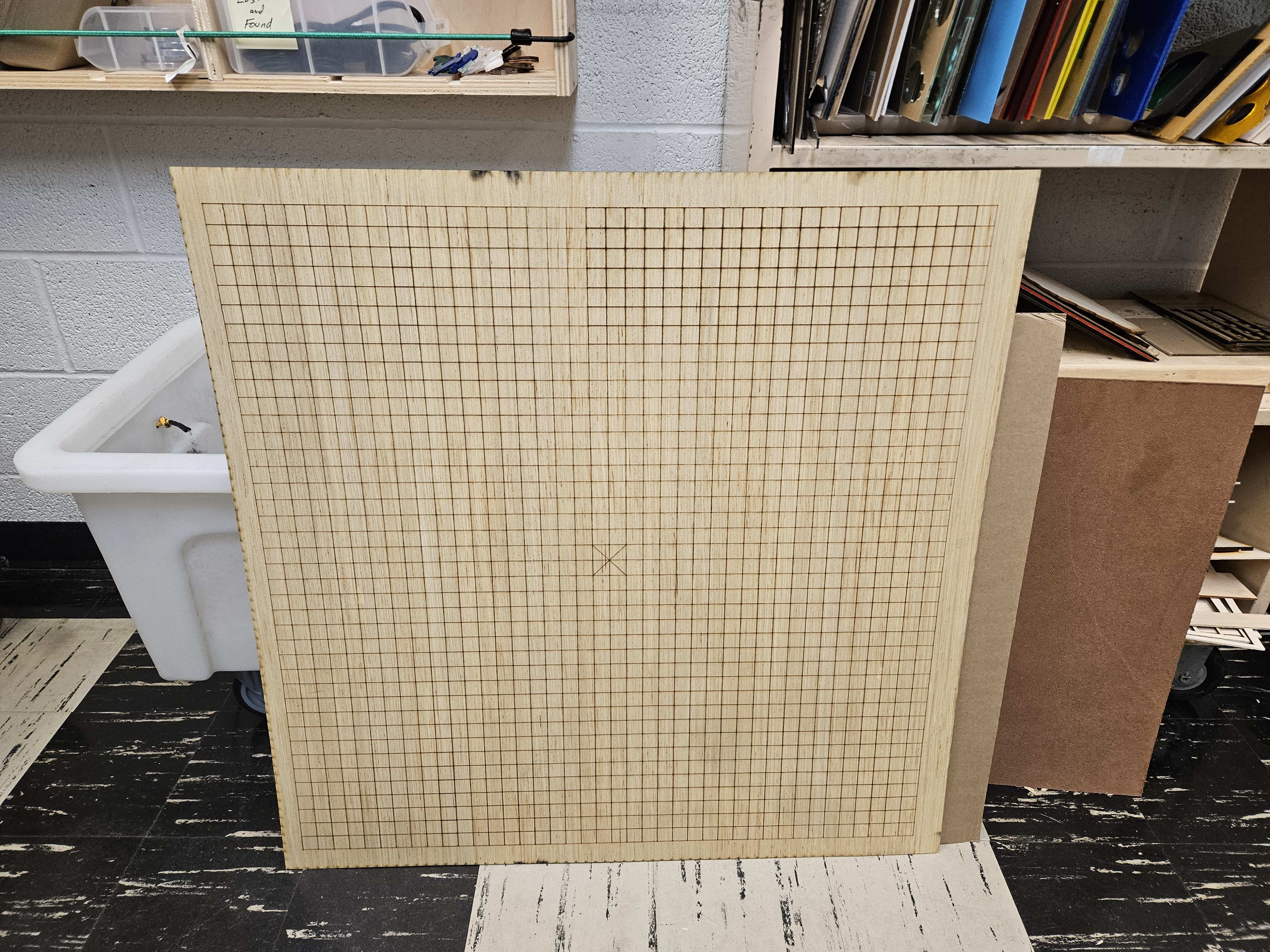
To add to this, I verified the robotics system. A maximum translation of 10cm takes at most 0.4s, which provides ample time. Secondly, I determined that grbl has a receiving buffer. In other words, it’s possible to enqueue several translation commands that the firmware will handle sequentially, and in order. This works nicely with our system that uses a Kalman Filter to generate increasingly better predictions incrementally as new frames are processed. Lastly, with the help of a MechE roommate, I acquired a base board around 3×3’ in area to ground the robot. An extensive grid was laser engraved onto the wood, with a special marking for the center, with 2cm separations. This will help with determining the location of the robot relative to the camera (and thus relative to the ball), as well as a good visual reference. We can mark out where the robot will rest every time.
Progress
Doing some final touches to the last presentation and getting ready to present it on Monday or Wednesday. I hope to support my other two teammates with concluding the rest of the system and with integrating with the robot. Integration should prove extremely straightforward.
As you’ve designed, implemented and debugged your project, what new tools or new knowledge did you find it necessary to learn to be able to accomplish these tasks? What learning strategies did you use to acquire this new knowledge?
Robotics as a whole was mostly unfamiliar to me. Even just driving a stepper motor was a leap for me. I think the Autodesk Instructables website was integral for my success in creating the robot. It lowers the skill floor required to implement a physical system, for which many ECE students (including myself) are not extremely familiar with. GRBL and CNC techniques were also new to me – I found online resources to be very useful, including the wiki pages for the grbl github repository that helped to explain some configurations I might be interested in. Capstone requires that you search on your own for resources and potential solutions; there isn’t a reference solution for you to ask TAs for. I felt I developed some independence in creating my robot. I think it’s important to realize that it’s okay to not have to build everything from scratch. Technology is developmental, continually building upon what is already there. No need to reinvent the wheel if the blueprint is right there in front of you.
The 2D ball detection has been completed, and we are now able to reliably detect the ball and generate x and y coordinates for the ball position within the frame of the camera. Jimmy had ironed out the Kalman filter detection code, and so I was able to successfully port that into the 2D detection file. With the Kalman function in, I made it so that when the ball is detected, a recording of the prediction and trajectory gets sent into a video file. We did a quick test, but it turns out that after adding the Kalman function, the FPS dropped down to about 15. This happens because within the code, a new frame is retrieved, then any processing we do on it (detect, then Kalman) will happen and needs to finish before a new frame can be retrieved. This causes the FPS to drop, to the point where the recorded video only spotted the ping pong ball for like 2-3 frames. This led to a pretty terrible Kalman prediction, which is understandable. This is concerning, but we knew that FPS would be an issue from the start. We are still confident that the Kalman prediction is correct, based on Jimmy’s testing with recorded videos. There are also numerous ways in which we can increase the FPS. For one, displaying the frame also takes computation power and slows down the rate of frame retrieval, and since displaying is purely for debugging or demonstration purposes, for actual runs of the system we don’t need to show the frame on a monitor. This reliably increases the FPS by 10+, based on some simple testing I did. Jimmy is also working on using threading to separate the frame retrieval and frame processing, which in theory should also give more frames.
For now the 2D work was done on my end, so I turned my attention to setting up the 3D detection and coordinate generation. This is entering a gray area, as none of us have had any experience working with the depth feature of the camera. I started by piggybacking an existing example that the depthAI library came with. This example worked with activating the left and right mono cameras as an additional stereo camera, to provide depth data of the whole frame. Then there was an ROI (region of interest) in which the depth values within the ROI would be displayed. This ROI is adjustable, and in the example you could move the ROI with the WASD keys. My idea was to activate the color camera at the same time, and use that to detect the ball. Once the ball is detected, move the ROI to where the ball is in order to get the 3D Z coordinate. I wrote out the code, and for the demo we were able to showcase the ball’s depth being reported as we moved it around on screen. There was also an issue with alignment of the two camera systems, but I was able to take some time and fix that. This was promising, but there was still more to do, as the returned depth is not the real world 3D Z coordinate, but the shortest distance from the camera to the ball. This is only speculation, and more rigorous testing needs to be done to determine if that is true. Currently I’ve figured out the math that would translate the shortest distance from camera into the real world 3D Z coordinate, and have been able to generate 3D coordinates of ball position while the camera is on.
Either way, we are mostly confident about our ability to generate 3D coordinates relative to the camera’s location. The next thing I did was to think through and create a real world coordinate system that the XY robot could also utilize. I wrote out a plan of integrating what we have with the Pi into the robot side, as that still wasn’t super developed yet. Josiah has done a good job with getting G-code to reliably run on the robot, so it is just a matter of accurately determining the landing coordinates and sending them over.
We are coming to the end of the semester, and even though there are still a few big question marks to tackle, we have set up quite a few work sessions to get it all done. I would say that we are currently on pace to finish within the next week or two, but will require a solid group effort to get it done.
As you’ve designed, implemented and debugged your project, what new tools or new knowledge did you find it necessary to learn to be able to accomplish these tasks? What learning strategies did you use to acquire this new knowledge? We recognize that there are quite a few different methods (i.e. learning strategies) for gaining new knowledge — one doesn’t always need to take a class, or read a textbook to learn something new. Informal methods, such as watching an online video or reading a forum post are quite appropriate learning strategies for the acquisition of new knowledge.
I had never worked with either the AMD KRIA or a Raspberry Pi before, so learning the respective tools to get that to work took significant time. I used Vivado and Vitis in the context of setting up the KRIA, and had to look through many AMD/Xilinx guides and forums in small bug encounters. For the Raspberry Pi (RPI), I also had to look through numerous guides and tutorials by RPI for setup and debugging issues (the forum was especially helpful with an issue I ran into with bootup, giving me the exact LED error code and solution). I also used online videos to give me a better sense of what the RPI is and what it is capable of. Then there were the numerous guide pages and forums that Luxonis had in regards to dealing with any code regarding the camera. I also had to rely on TA help from both Varun and Nathan, who had expertise in the KRIA and RPI/OAK-D camera respectively, for other small issues that online resources couldn’t satisfy me for.
Accomplishments
After experimenting and working with the current kalman filter, I decided to scrap this implementation and work on a new self-implementation of the filter using the numpy library. This yielded really good results, as it allowed me to tune specific parameters that the other model wouldn’t have otherwise. It was able to predict very accurately from visual inspection, although testing will need to be done to make sure that the predictions can be made consistently from different throws and with many variables involved. Also this week Gordon and I together did work on bringing up the OAK-D camera to use on the RPI. There were some issues with the frame rate of the camera, which I aim to resolve using multithreading so that the detection and prediction processing will occur concurrently with pulling in the frames from the camera’s feed.
Schedule
Although I have finished the 2D kalman filter to a very satisfactory level, progress on the 3D kalman filter needs to be done. Things will hopefully be sped up now that Gordon will also be working on onboarding the camera with the RPi so that I can focus all my attention on the algorithmic portion. However, I feel comfortable with the progress that we’re at because the 2D kalman filter can always be used as a fallback incase anything goes wrong with the 3D kalman filter.
Deliverables
Effort will now be made to transition to the 3D kalman filter. I will need to order the white background sheet and stands so that we can accurately replicate the favourable conditions that was used in the original test video so that our camera system will be able to accurately detect and predict the ball. Once the background has come in, I will be able to start recording videos that can be used for the verification stages of the project (see below).
Testing for detection pipeline
Testing for the prediction pipeline (kalman filter)